Variety STeamer
Operation
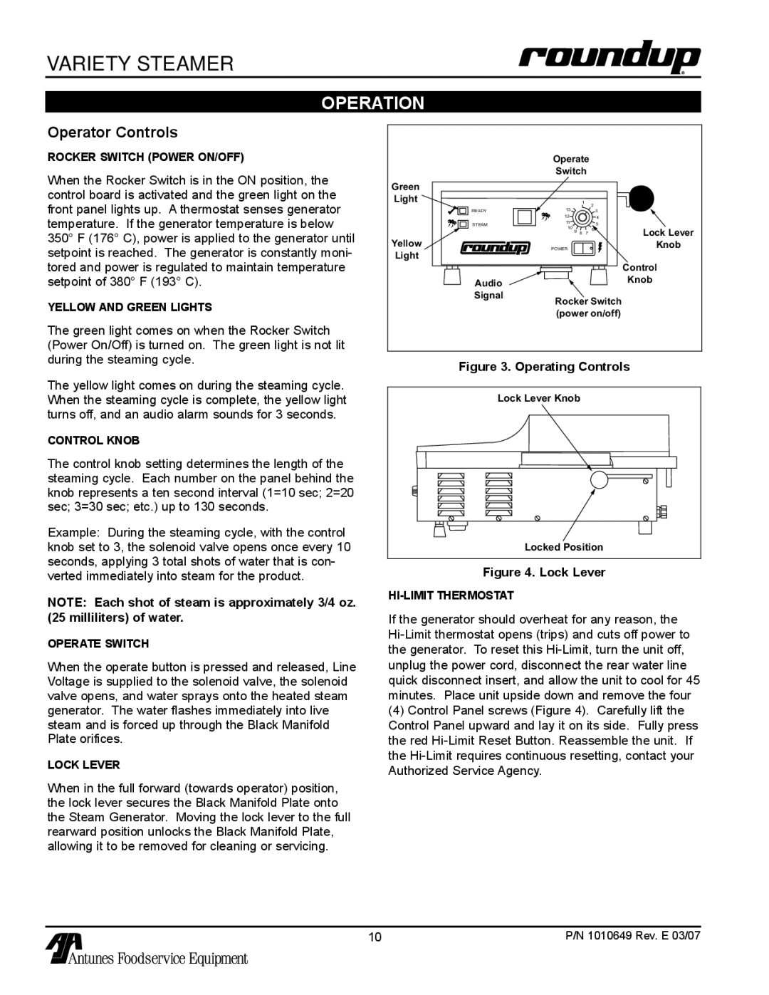
Operator Controls
Rocker Switch (Power On/Off)
When the Rocker Switch is in the ON position, the control board is activated and the green light on the front panel lights up. A thermostat senses generator temperature. If the generator temperature is below 350° F (176° C), power is applied to the generator until setpoint is reached. The generator is constantly moni- tored and power is regulated to maintain temperature setpoint of 380° F (193° C).
Yellow and green lights
The green light comes on when the Rocker Switch (Power On/Off) is turned on. The green light is not lit during the steaming cycle.
The yellow light comes on during the steaming cycle. When the steaming cycle is complete, the yellow light turns off, and an audio alarm sounds for 3 seconds.
Control knob
The control knob setting determines the length of the steaming cycle. Each number on the panel behind the knob represents a ten second interval (1=10 sec; 2=20 sec; 3=30 sec; etc.) up to 130 seconds.
Example: During the steaming cycle, with the control knob set to 3, the solenoid valve opens once every 10 seconds, applying 3 total shots of water that is con- verted immediately into steam for the product.
NOTE: Each shot of steam is approximately 3/4 oz. (25 milliliters) of water.
Operate switch
When the operate button is pressed and released, Line Voltage is supplied to the solenoid valve, the solenoid valve opens, and water sprays onto the heated steam generator. The water flashes immediately into live steam and is forced up through the Black Manifold Plate orifices.
Lock Lever
When in the full forward (towards operator) position, the lock lever secures the Black Manifold Plate onto the Steam Generator. Moving the lock lever to the full rearward position unlocks the Black Manifold Plate, allowing it to be removed for cleaning or servicing.
| Operate |
|
| ||
| Switch |
|
| ||
Green |
|
|
|
|
|
Light |
|
| 1 | 2 |
|
| 13 |
|
|
| |
READY |
|
| 3 |
| |
| 12 |
|
| 4 |
|
STEAM | 11 |
|
| 5 |
|
10 9 |
|
| Lock Lever | ||
| 8 | 7 | 6 | ||
Yellow |
|
|
|
| |
POWER |
|
|
| Knob | |
Light |
|
|
|
|
|
|
|
|
|
| Control |
Audio |
|
|
|
| Knob |
|
|
|
|
| |
Signal | Rocker Switch |
| |||
|
| ||||
| (power on/off) |
| |||
Figure 3. Operating Controls
Lock Lever Knob |
Locked Position |
Figure 4. Lock Lever
If the generator should overheat for any reason, the
(4)Control Panel screws (Figure 4). Carefully lift the Control Panel upward and lay it on its side. Fully press the red
10 | P/N 1010649 Rev. E 03/07 |
