7000 specifications
The APC 7000, a renowned product from APC by Schneider Electric, represents a significant advancement in the realm of power conditioning and management. This high-performance uninterruptible power supply (UPS) is engineered to provide reliable and comprehensive protection for critical equipment in various environments, from small businesses to large enterprises.One of the main features of the APC 7000 is its robust power management capabilities. With an impressive output capacity, this UPS ensures that devices remain powered during outages or fluctuations in voltage. The incorporation of Advanced Battery Management technology maximizes battery life and efficiency, providing users with longer operational time during power disturbances.
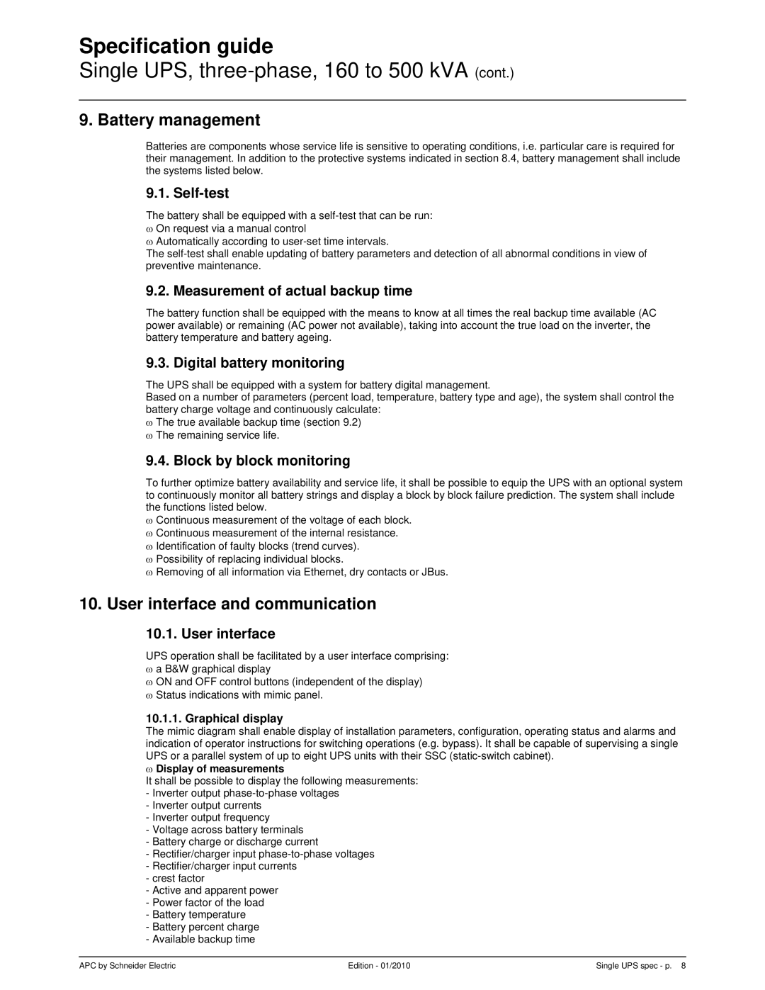
The APC 7000 also boasts a user-friendly LCD display, which provides real-time information on the UPS status, including power usage, battery health, and load levels. This intuitive interface allows users to monitor performance at a glance and facilitates easy navigation through the system settings.
In addition to its monitoring capabilities, the APC 7000 integrates SmartSlot technology. This feature enables users to customize the UPS with additional management cards, enhancing its functionality. Users can choose from various options such as network management cards, which allow remote monitoring and control, or environmental monitoring cards that track temperature and humidity levels.
Built with scalability in mind, the APC 7000 supports external battery packs, allowing for increased runtime. This is particularly vital for businesses with extended operational needs during outages. The system also includes intelligent cooling and a heat-sensitive fan, which adjusts its operation based on the load and temperature, thus optimizing performance while reducing noise levels.
Furthermore, the APC 7000 is equipped with multiple output options, including programmable outlets. This feature enables users to manage power distribution efficiently, ensuring essential devices remain operational while less critical equipment can be powered down to conserve battery life.
With its blend of cutting-edge technologies and robust features, the APC 7000 stands out as a reliable powerhouse that meets the demands of modern power protection. Its commitment to performance, user-centric design, and scalability make it an indispensable asset for organizations looking to maintain uptime and safeguard their critical operations. By providing exceptional efficiency and reliable service, the APC 7000 solidifies its position as a leading choice among UPS solutions in today's dynamic technology landscape.

