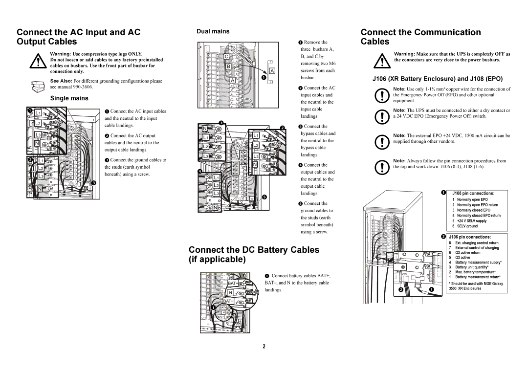
Connect the AC Input and AC Output Cables
Warning: Use compression type lugs ONLY.
Do not loosen or add cables to any factory preinstalled cables on busbars. Use the front part of busbar for connection only.
See Also: For different grounding configurations please see manual
Dual mains
Remove the
three busbars A,
B, and C by
removing two M6
screws from each
busbar.
Connect the AC input cables and
Connect the Communication Cables
Warning: Make sure that the UPS is completely OFF as the connectors are very close to the power busbars.
J106 (XR Battery Enclosure) and J108 (EPO)
Note: Use only
Single mains
|
Connect the AC input cables |
and the neutral to the input |
the neutral to the input cable landings.
equipment.
Note: The UPS must be connected to either a dry contact or a 24 VDC EPO (Emergency Power Off) switch.
|
|
cable landings. |
Connect the AC output cables and the neutral to the output cable landings.
Connect the ground cables to the studs (earth symbol beneath) using a screw.
| Connect the |
|
| |
|
|
| ||
| bypass cables and | Note: The external EPO +24 VDC, 1500 mA circuit can be | ||
| the neutral to the | |||
| supplied through other vendors. | |||
| bypass cable |
|
| |
| landings. | Note: Always follow the pin connection procedures from | ||
| Connect the | |||
| the top and work down: J106 | |||
| output cables and | |||
|
| |||
| the neutral to the |
|
| |
| output cable |
|
| |
| landings. | | J108 pin connections: | |
|
| 1 Normally open EPO | ||
| Connect the |
| ||
|
| 2 Normally open EPO return | ||
| ground cables to |
| 3 Normally closed EPO | |
| the studs (earth |
| 4 Normally closed EPO return | |
|
| 5 +24 V SELV supply | ||
| symbol beneath) |
| ||
|
| 6 SELV ground | ||
| using a screw. | J106 pin connections: | ||
|
| |||
Connect the DC Battery Cables | 8 Ext. charging control return | |||
6 | Q3 active return | |||
(if applicable) |
| 7 External control of charging | ||
| 4 | Battery measurement supply* | ||
|
| 5 | Q3 active | |
|
| 3 | Battery unit quantity* | |
Connect battery cables BAT+, | 2 | Max. battery temperature* | ||
1 | Battery measurement return* | |||
|
| * Should be used with MGE Galaxy | |
landings. | | | 3500 XR Enclosures |
|
|
|
|
2