® Back-UPS® ES 450/550G
User Guide
www.apc.com
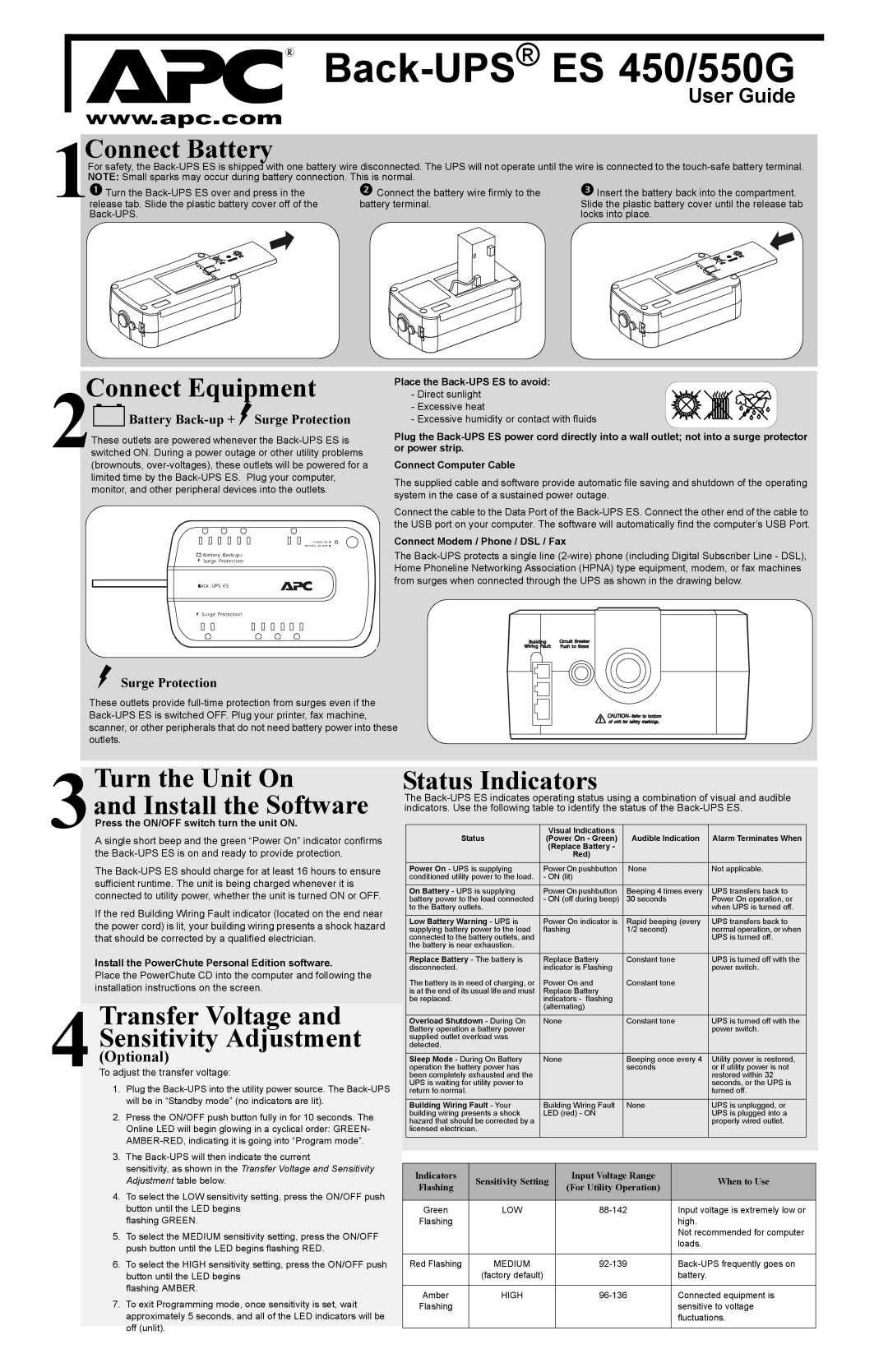
1 | Connect Battery |
|
|
|
|
|
| ||
For safety, the | |||||||||
NOTE: Small sparks may occur during battery connection. This is normal. |
|
|
| ||||||
Turn the | Connect the battery wire firmly to the | Insert the battery back into the compartment. | |||||||
release tab. Slide the plastic battery cover off of the | battery terminal. | Slide the plastic battery cover until the release tab | |||||||
|
|
| locks into place. | ||||||
|
|
|
|
|
|
|
|
|
|
|
|
|
|
|
|
|
|
|
|
|
|
|
|
|
|
|
|
|
|
|
|
|
|
|
|
|
|
|
|
Connect Equipment
2
 Battery
 Back-up +  Surge Protection
These outlets are powered whenever the
Place the
- Direct sunlight - Excessive heat
- Excessive humidity or contact with fluids
Plug the
Connect Computer Cable
The supplied cable and software provide automatic file saving and shutdown of the operating system in the case of a sustained power outage.
Connect the cable to the Data Port of the
Connect Modem / Phone / DSL / Fax
The
Surge Protection
These outlets provide
3Turn the Unit On
and Install the Software
Press the ON/OFF switch turn the unit ON.
A single short beep and the green “Power On” indicator confirms the
The
If the red Building Wiring Fault indicator (located on the end near the power cord) is lit, your building wiring presents a shock hazard that should be corrected by a qualified electrician.
Install the PowerChute Personal Edition software.
Place the PowerChute CD into the computer and following the installation instructions on the screen.
4Transfer Voltage and Sensitivity Adjustment
(Optional)
To adjust the transfer voltage:
1.Plug the
2.Press the ON/OFF push button fully in for 10 seconds. The Online LED will begin glowing in a cyclical order: GREEN-
3.The
sensitivity, as shown in the Transfer Voltage and Sensitivity Adjustment table below.
4.To select the LOW sensitivity setting, press the ON/OFF push button until the LED begins
flashing GREEN.
5.To select the MEDIUM sensitivity setting, press the ON/OFF push button until the LED begins flashing RED.
6.To select the HIGH sensitivity setting, press the ON/OFF push button until the LED begins
flashing AMBER.
7.To exit Programming mode, once sensitivity is set, wait approximately 5 seconds, and all of the LED indicators will be off (unlit).
Status Indicators
The
Status | Visual Indications | Audible Indication | Alarm Terminates When |
(Power On - Green) | |||
| (Replace Battery - |
|
|
| Red) |
|
|
|
|
|
|
Power On - UPS is supplying | Power On pushbutton | None | Not applicable. |
conditioned utility power to the load. | - ON (lit) |
|
|
|
|
|
|
On Battery - UPS is supplying | Power On pushbutton | Beeping 4 times every | UPS transfers back to |
battery power to the load connected | - ON (off during beep) | 30 seconds | Power On operation, or |
to the Battery outlets. |
|
| when UPS is turned off. |
|
|
|
|
Low Battery Warning - UPS is | Power On indicator is | Rapid beeping (every | UPS transfers back to |
supplying battery power to the load | flashing | 1/2 second) | normal operation, or when |
connected to the battery outlets, and |
|
| UPS is turned off. |
the battery is near exhaustion. |
|
|
|
|
|
|
|
Replace Battery - The battery is | Replace Battery | Constant tone | UPS is turned off with the |
disconnected. | indicator is Flashing |
| power switch. |
The battery is in need of charging, or | Power On and | Constant tone |
|
is at the end of its usual life and must | Replace Battery |
|
|
be replaced. | indicators - flashing |
|
|
| (alternating) |
|
|
|
|
|
|
Overload Shutdown - During On | None | Constant tone | UPS is turned off with the |
Battery operation a battery power |
|
| power switch. |
supplied outlet overload was |
|
|
|
detected. |
|
|
|
|
|
|
|
Sleep Mode - During On Battery | None | Beeping once every 4 | Utility power is restored, |
operation the battery power has |
| seconds | or if utility power is not |
been completely exhausted and the |
|
| restored within 32 |
UPS is waiting for utility power to |
|
| seconds, or the UPS is |
return to normal. |
|
| turned off. |
|
|
|
|
Building Wiring Fault - Your | Building Wiring Fault | None | UPS is unplugged, or |
building wiring presents a shock | LED (red) - ON |
| UPS is plugged into a |
hazard that should be corrected by a |
|
| properly wired outlet. |
licensed electrician. |
|
|
|
|
|
|
|
Indicators | Sensitivity Setting | Input Voltage Range | When to Use | |
Flashing | (For Utility Operation) | |||
|
| |||
|
|
|
| |
Green | LOW | Input voltage is extremely low or | ||
Flashing |
|
| high. | |
|
|
| Not recommended for computer | |
|
|
| loads. | |
|
|
|
| |
Red Flashing | MEDIUM | |||
| (factory default) |
| battery. | |
|
|
|
| |
Amber | HIGH | Connected equipment is | ||
Flashing |
|
| sensitive to voltage | |
|
|
| fluctuations. | |
|
|
|
|