APPENDIX A: ELECTRICAL WIRING CHECKLIST
Complete this checklist to ensure that the Symmetra RM has been wired properly.
Ensure that all switches (system enable, maintenance bypass, input circuit breaker, and bypass circuit breaker) are in the Off or Stand By position. Turn off or unplug all equipment connected to the Symmetra RM.
Ensure that the input voltage selection switch is in the appropriate position.
1.Apply power to the system input. Measure the voltage at the input terminal block. Record the measured voltages:
OR
The measured voltage must be between 184 and 265 V. If it is not, do not continue! Verify the wiring from the power source to the input wiring connections. Repeat step 1.
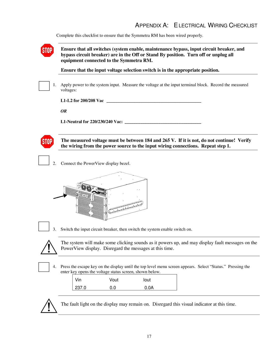
2. Connect the PowerView display bezel.
3. Switch the input circuit breaker, then switch the system enable switch on.
The system will make some clicking sounds as it powers up, and may display fault messages on the PowerView display. Disregard the messages at this time.
4.Press the escape key on the display until the top level menu screen appears. Select “Status.” Pressing the enter key opens the voltage status screen, shown below.
| Vin | Vout | Iout |
|
| 237.0 | 0.0 | 0.0A |
|
|
|
|
|
|
The fault light on the display may remain on. Disregard this visual indicator at this time.
17
