Product Overview
Front View Component Identification |
|
|
|
|
| • |
|
| Œ | Ž | • |
|
|
| |
| • |
| • |
“ |
|
| |
|
|
| |
‘ | • |
| • |
|
| ||
’ | • |
|
|
|
| • | |
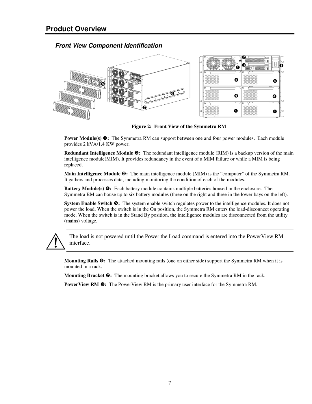
Figure 2: Front View of the Symmetra RM |
|
|
|
Power Module(s) Œ: The Symmetra RM can support between one and four power modules. Each module provides 2 kVA/1.4 KW power.
Redundant Intelligence Module •: The redundant intelligence module (RIM) is a backup version of the main intelligence module(MIM). It provides redundancy in the event of a MIM failure or while a MIM is being replaced.
Main Intelligence Module Ž: The main intelligence module (MIM) is the “computer” of the Symmetra RM. It gathers and processes data, including monitoring the condition of each of the modules.
Battery Module(s) •: Each battery module contains multiple batteries housed in the enclosure. The Symmetra RM can house up to six battery modules (three on the right and three in the lower bays on the left).
System Enable Switch •: The system enable switch regulates power to the intelligence modules. It does not power the load. When the switch is in the On position, the Symmetra RM enters the
The load is not powered until the Power the Load command is entered into the PowerView RM interface.
Mounting Rails ‘: The attached mounting rails (one on either side) support the Symmetra RM when it is mounted in a rack.
Mounting Bracket ’: The mounting bracket allows you to secure the Symmetra RM in the rack.
PowerView RM “: The PowerView RM is the primary user interface for the Symmetra RM.
7
