1.Stand-by / On Indicator
The LED indicates whether the unit is in stand-by mode or operational. It will be illuminated red when in stand-by, and green when operational
2.Crossover Frequency Control
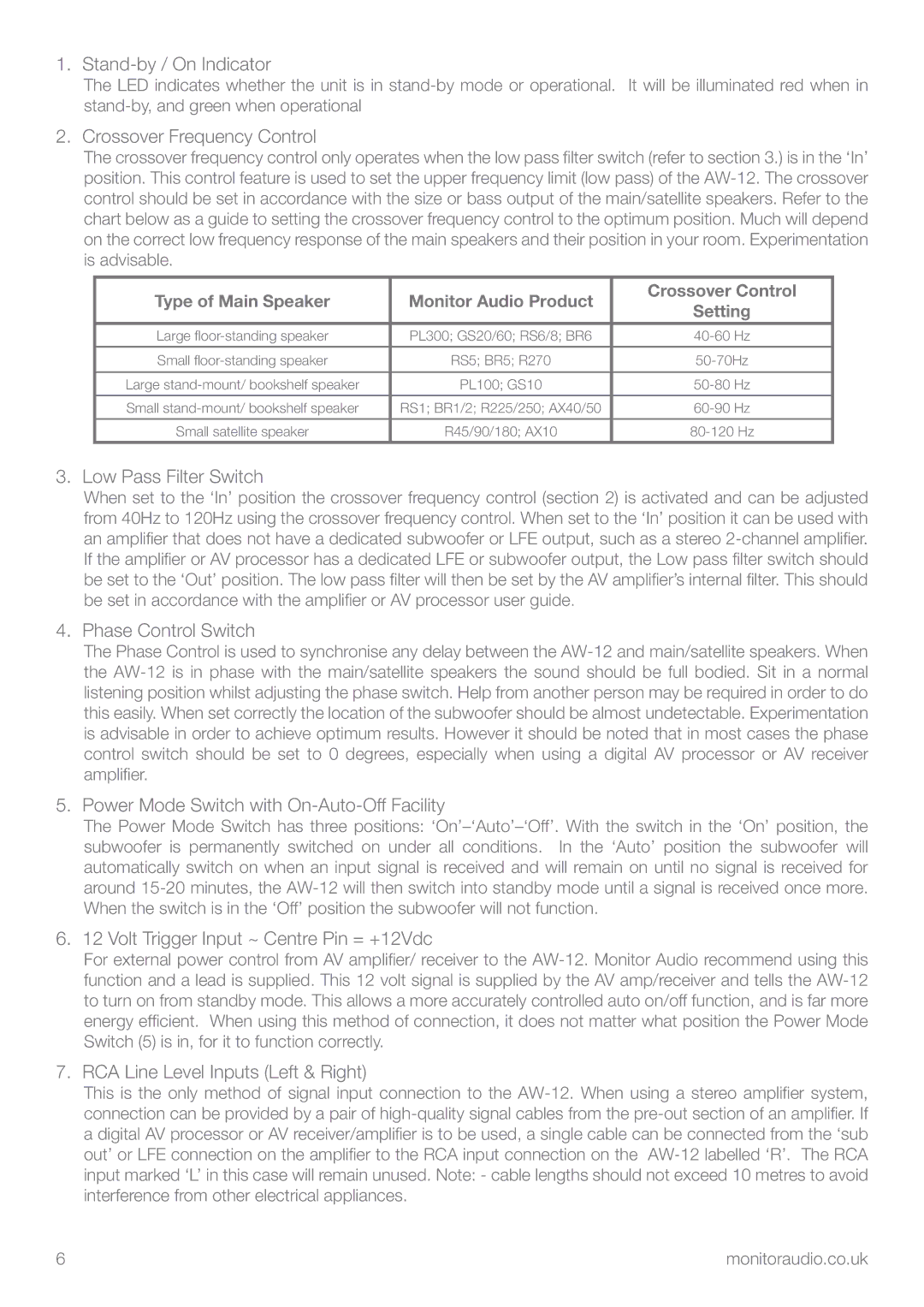
The crossover frequency control only operates when the low pass filter switch (refer to section 3.) is in the ‘In’ position. This control feature is used to set the upper frequency limit (low pass) of the AW-12. The crossover control should be set in accordance with the size or bass output of the main/satellite speakers. Refer to the chart below as a guide to setting the crossover frequency control to the optimum position. Much will depend on the correct low frequency response of the main speakers and their position in your room. Experimentation is advisable.
| Type of Main Speaker | Monitor Audio Product | Crossover Control |
| Setting |
| | |
| Large floor-standing speaker | PL300; GS20/60; RS6/8; BR6 | 40-60 Hz |
| | | |
| Small floor-standing speaker | RS5; BR5; R270 | 50-70Hz |
| | | |
| Large stand-mount/ bookshelf speaker | PL100; GS10 | 50-80 Hz |
| | | |
| Small stand-mount/ bookshelf speaker | RS1; BR1/2; R225/250; AX40/50 | 60-90 Hz |
| | | |
| Small satellite speaker | R45/90/180; AX10 | 80-120 Hz |
3.Low Pass Filter Switch
When set to the ‘In’ position the crossover frequency control (section 2) is activated and can be adjusted from 40Hz to 120Hz using the crossover frequency control. When set to the ‘In’ position it can be used with an amplifier that does not have a dedicated subwoofer or LFE output, such as a stereo 2-channel amplifier. If the amplifier or AV processor has a dedicated LFE or subwoofer output, the Low pass filter switch should be set to the ‘Out’ position. The low pass filter will then be set by the AV amplifier’s internal filter. This should be set in accordance with the amplifier or AV processor user guide.
4.Phase Control Switch
The Phase Control is used to synchronise any delay between the AW-12 and main/satellite speakers. When the AW-12 is in phase with the main/satellite speakers the sound should be full bodied. Sit in a normal listening position whilst adjusting the phase switch. Help from another person may be required in order to do this easily. When set correctly the location of the subwoofer should be almost undetectable. Experimentation is advisable in order to achieve optimum results. However it should be noted that in most cases the phase control switch should be set to 0 degrees, especially when using a digital AV processor or AV receiver amplifier.
5.Power Mode Switch with On-Auto-Off Facility
The Power Mode Switch has three positions: ‘On’–‘Auto’–‘Off’. With the switch in the ‘On’ position, the subwoofer is permanently switched on under all conditions. In the ‘Auto’ position the subwoofer will automatically switch on when an input signal is received and will remain on until no signal is received for around 15-20 minutes, the AW-12 will then switch into standby mode until a signal is received once more. When the switch is in the ‘Off’ position the subwoofer will not function.
6.12 Volt Trigger Input ~ Centre Pin = +12Vdc
For external power control from AV amplifier/ receiver to the AW-12. Monitor Audio recommend using this function and a lead is supplied. This 12 volt signal is supplied by the AV amp/receiver and tells the AW-12 to turn on from standby mode. This allows a more accurately controlled auto on/off function, and is far more energy efficient. When using this method of connection, it does not matter what position the Power Mode Switch (5) is in, for it to function correctly.
7.RCA Line Level Inputs (Left & Right)
This is the only method of signal input connection to the AW-12. When using a stereo amplifier system, connection can be provided by a pair of high-quality signal cables from the pre-out section of an amplifier. If a digital AV processor or AV receiver/amplifier is to be used, a single cable can be connected from the ‘sub out’ or LFE connection on the amplifier to the RCA input connection on the AW-12 labelled ‘R’. The RCA input marked ‘L’ in this case will remain unused. Note: - cable lengths should not exceed 10 metres to avoid interference from other electrical appliances.