Manuals
/
Aprilaire
/
Household Appliance
/
Thermostat
Aprilaire
Model 8570
installation instructions
Diagram 7 Two-Stage Heat Pump
Models:
Model 8570
1
19
40
40
Download
40 pages
3.62 Kb
16
17
18
19
20
21
22
23
Troubleshooting
Specs
Diagram 4 Boiler with AC
Wire Requirements
Progressive Recovery
Safety
Page 19
Image 19
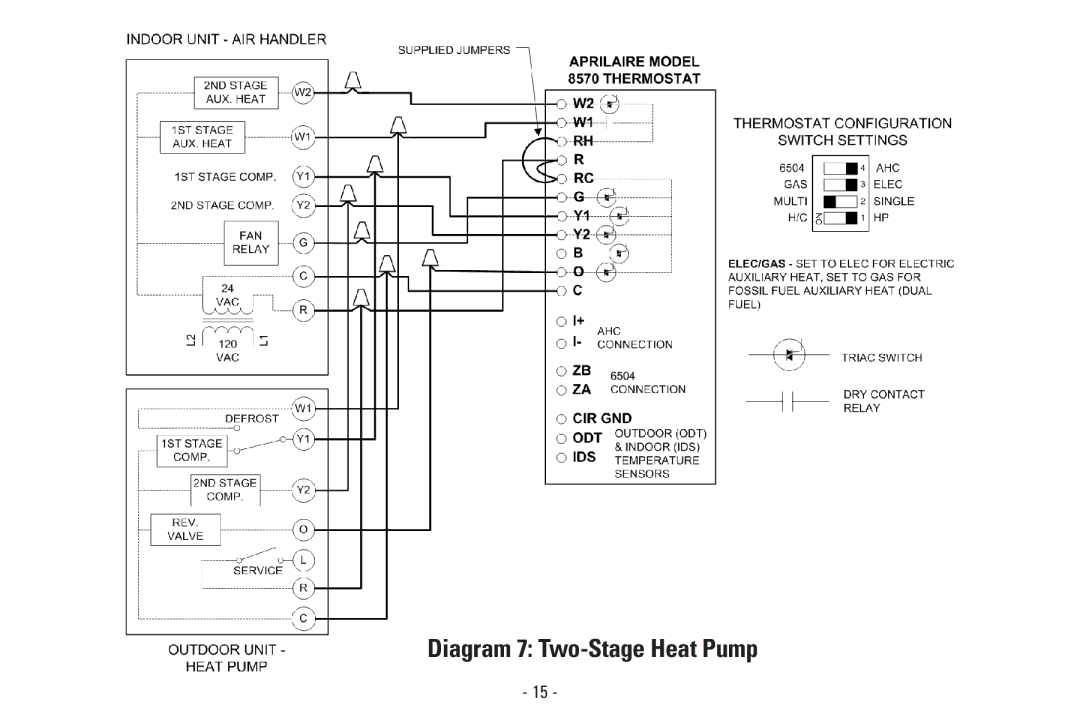
Diagram 7:
Two-Stage
Heat Pump
- 15 -
Page 18
Page 20
Page 19
Image 19
Page 18
Page 20
Contents
Instructions
Table of Contents
Heat Pumps Only
Thermostat Startup
Safety Instructions
Model 8570 Specifications
Single-Stage Heat Pump Two-Stage Heat Pump
Wire Requirements
Two-Stage Furnace/AC
Radiant 1st Stage Heat
Keep the thermostat 18 from an outside wall
Select a Mounting Location
Open the Thermostat
Mount the Thermostat Base to the Wall
AHC
Set to HP when installed with heat pumps
Run a cable with the correct number of wires
Wire the Thermostat to the Hvac Equipment
Diagram 1 Single-Stage Furnace and AC
Diagram 2 Two-Stage Furnace and AC
Diagram 3 Two-Stage Roof Top Unit
Diagram 4 Boiler with AC
Page
Diagram 6 Single-Stage Heat Pump
Diagram 7 Two-Stage Heat Pump
Mount above anticipated snow line
Mount the outdoor temperature sensor see Figure
85.4
230.6
163.8
117.6
IDS ODT CIR GND
Mount the AHC and its outdoor temperature sensor
Optional Install AN Automatic Humidifier Control AHC
+ I- R C H ODT
Mount the indoor temperature sensor
IDS ODT CIR GND
Thermostat Startup Stand Alone Applications
From the Main Screen, press the Info button
Check FAN Operation
Troubleshooting AHC Connection
Check Heating Operation
Troubleshooting Heating Operation
Thermostat does not call for cooling
Troubleshooting Cooling Operation
To Cool and make a call for cooling
To Emergency Heat and make a call for heat
Check Emergency Heat Operation Heat Pumps Only
Differential
Customize the Application Settings
Display will show the ADV. Settings Menu
Progressive Recovery
Offset
Range is 0F to 40F
Balance Points Heat Pumps only
To delete a character, press the Back button
Input Dealer Contact Information
To delete a number, press the Back button
Blower Extension for Humidity Control
Press the Menu button
DP #10006198 B2203358A BOX 1467 MADISON, WI
Top
Page
Image
Contents