Instructions
READ AND SAVE THESE INSTRUCTIONS
Safety & Installation
Model
Diagram 5 - Radiant Floor 1st Stage Heat
TABLE OF CONTENTS
5. WIRE THE THERMOSTAT TO THE
6. OPTIONAL - INSTALL AN OUTDOOR
10. CUSTOMIZE THE
Monitors - Air Filter, Service Humidifier UV Lamp, Service HVAC
Check Emergency Heat Operation
Verify Outdoor Temperature Sensor Check Fan Operation
SAFETY INSTRUCTIONS
Electrical
MODEL 8570 SPECIFICATIONS
Thermal
Diagram Page
WIRE REQUIREMENTS
# Wires
Figure 1 - Thermostat Wire
If installing an indoor temperature sensor…
If installing the thermostat alone…
1 SELECT A MOUNTING LOCATION
2 OPEN THE THERMOSTAT
Drill a 3/16 hole for wall anchors
3 MOUNT THE THERMOSTAT BASE TO THE WALL
Drill a 3/32 starter hole for screws only
ELEC
4 SET THE CONFIGURATION DIP SWITCHES ON THE THERMOSTAT CIRCUIT BOARD
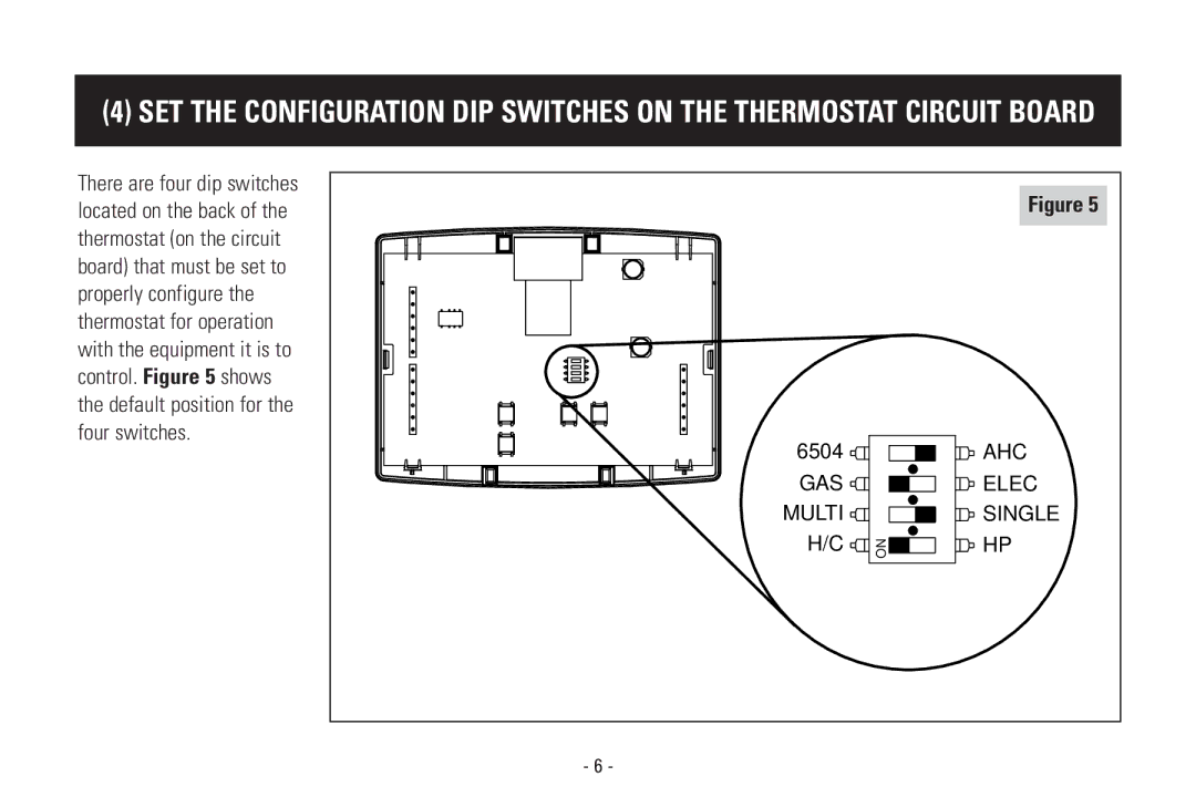
6504
MULTI
Set to ELEC when the heat source is electric such as strip heat
# Wires
5 WIRE THE THERMOSTAT TO THE HVAC EQUIPMENT
Application
Diagram 1 Single-Stage Furnace and AC
Diagram 2 Two-Stage Furnace and AC
Diagram 3 Two-Stage Roof Top Unit
Diagram 4 Boiler with AC
Page
Diagram 6 Single-Stage Heat Pump
Diagram 7 Two-Stage Heat Pump
Mount above anticipated snow line
1. Mount the outdoor temperature sensor see Figure
Maximum wire length from sensor to thermostat is 300 feet
NORTH, EAST
4. Wire the sensor to the thermostat see Figure
ZA ZB C
IDS ODT CIR GND
7 OPTIONAL - INSTALL AN AUTOMATIC HUMIDIFIER CONTROL AHC
AHC through furnace accessory terminals
AUTOMATIC MODE
POWER
I+ I- R C H ODT
BYPASS
Do not run the wire along
2. Run a 2-wire cable from the sensor to the thermostat
Locate the sensor as you would locate a thermostat
ZA ZB C
IDS ODT CIR GND
MESSAGE
9 THERMOSTAT STARTUP - STAND ALONE APPLICATIONS
SETPOINTS ROOM TEMPERATURE
CENTER
1. PLACE THE THERMOSTAT ON THE BASE
TROUBLESHOOTING - AHC CONNECTION
Symptom
Cause
The B terminal will energize when in the Heat mode
Symptom
TROUBLESHOOTING - HEATING OPERATION
Cause
Cause
TROUBLESHOOTING - COOLING OPERATION
Symptom
Minimum-off times. Change the mode to OFF first, then change the mode
TROUBLESHOOTING - EMERGENCY HEAT OPERATION
Symptom
Cause
1. DIFFERENTIAL
10 CUSTOMIZE THE APPLICATION SETTINGS
2. Press and hold both the and buttons for 3 seconds
2. OFFSET
3. PROGRESSIVE RECOVERY
2. Press and hold both the and buttons for 3 seconds
4. BALANCE POINTS HEAT PUMPS ONLY
6. To enter a letter in the name of the company, use the
5. INPUT DEALER CONTACT INFORMATION
2. Press and hold both the and buttons for 3 seconds
6. BLOWER EXTENSION FOR HUMIDITY CONTROL
7. MONITORS - AIR FILTER, SERVICE HUMIDIFIER, UV LAMP, SERVICE HVAC
To set humidifier, filter, UV and HVAC service reminder schedules
P.O. BOX 1467 MADISON, WI
DP #10006198
B2203358A
Printed in U.S.A