WIRE REQUIREMENTS
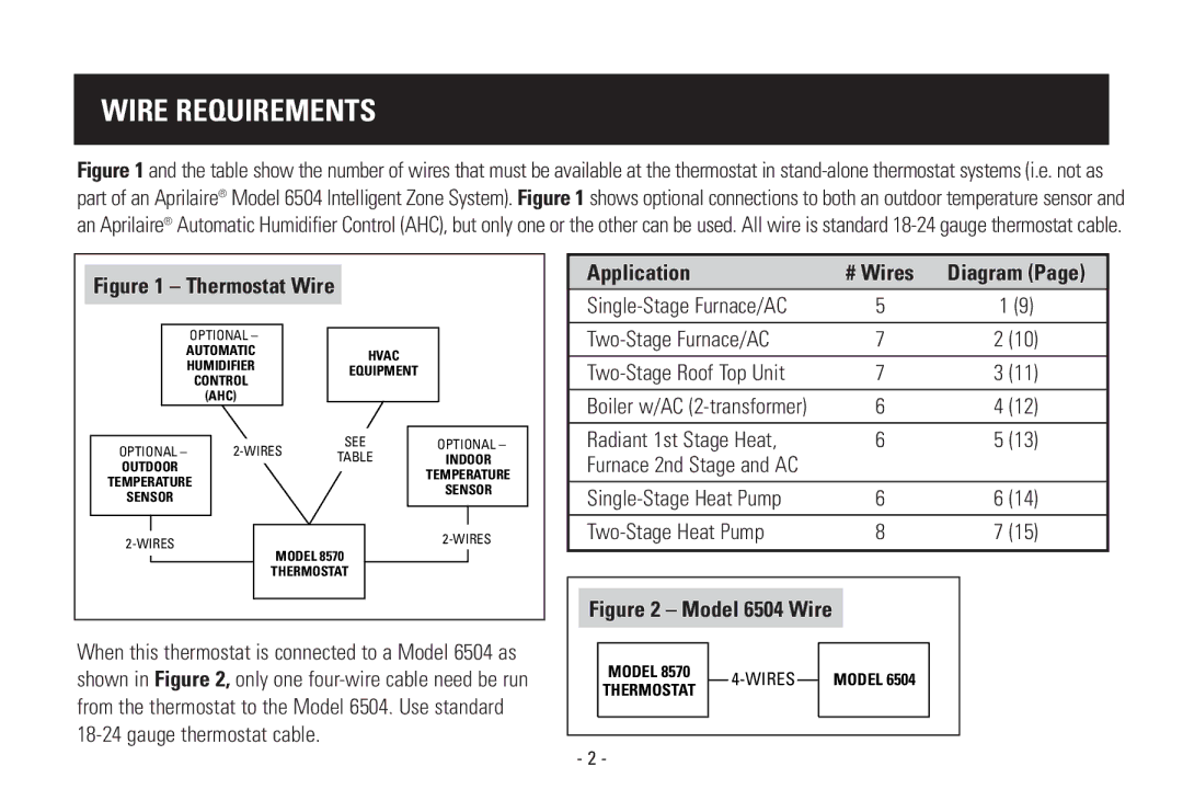
Figure 1 and the table show the number of wires that must be available at the thermostat in stand-alone thermostat systems (i.e. not as part of an Aprilaire® Model 6504 Intelligent Zone System). Figure 1 shows optional connections to both an outdoor temperature sensor and an Aprilaire® Automatic Humidifier Control (AHC), but only one or the other can be used. All wire is standard 18-24 gauge thermostat cable.
Figure 1 – Thermostat Wire |
|
| |||
| OPTIONAL – |
|
|
| |
AUTOMATIC |
| HVAC |
| ||
HUMIDIFIER |
|
| |||
| EQUIPMENT |
| |||
| CONTROL |
|
| ||
|
|
|
| ||
| (AHC) |
|
|
| |
OPTIONAL – | SEE | OPTIONAL – | |||
TABLE | INDOOR | ||||
OUTDOOR |
|
| |||
|
|
| TEMPERATURE | ||
TEMPERATURE |
|
| |||
|
| SENSOR | |||
SENSOR |
|
|
| ||
|
|
|
| ||
|
|
| |||
| MODEL 8570 |
| |||
|
|
| |||
|
| THERMOSTAT |
| ||
When this thermostat is connected to a Model 6504 as shown in Figure 2, only one
| Application |
|
|
|
|
| # Wires | Diagram (Page) | ||
| 5 | 1 (9) | ||||||||
|
|
|
|
| ||||||
|
| 7 | 2 (10) | |||||||
|
|
|
|
| ||||||
| 7 | 3 (11) | ||||||||
| Boiler w/AC | 6 | 4 (12) | |||||||
|
|
|
|
| ||||||
| Radiant 1st Stage Heat, | 6 | 5 (13) | |||||||
| Furnace 2nd Stage and AC |
|
|
|
| |||||
|
| 6 | 6 (14) | |||||||
|
| 8 | 7 (15) | |||||||
|
|
|
|
|
|
|
|
|
|
|
|
|
|
|
|
| |||||
|
|
|
|
|
| |||||
| Figure 2 – Model 6504 Wire |
|
|
|
| |||||
|
|
|
|
|
|
|
|
|
|
|
|
| MODEL 8570 |
|
|
|
|
|
|
|
|
|
|
|
|
| MODEL 6504 |
|
| |||
|
| THERMOSTAT |
|
|
|
|
| |||
|
|
|
|
|
|
|
|
|
| |
|
|
|
|
|
|
|
|
|
|
|
|
|
|
|
|
|
|
|
|
|
|
- 2 -
