INSTALLATION INSTRUCTIONS
POSITIONING AND SET-UP FOR USE
1)Place the machine in its place of intended use in compliance with the following instructions:
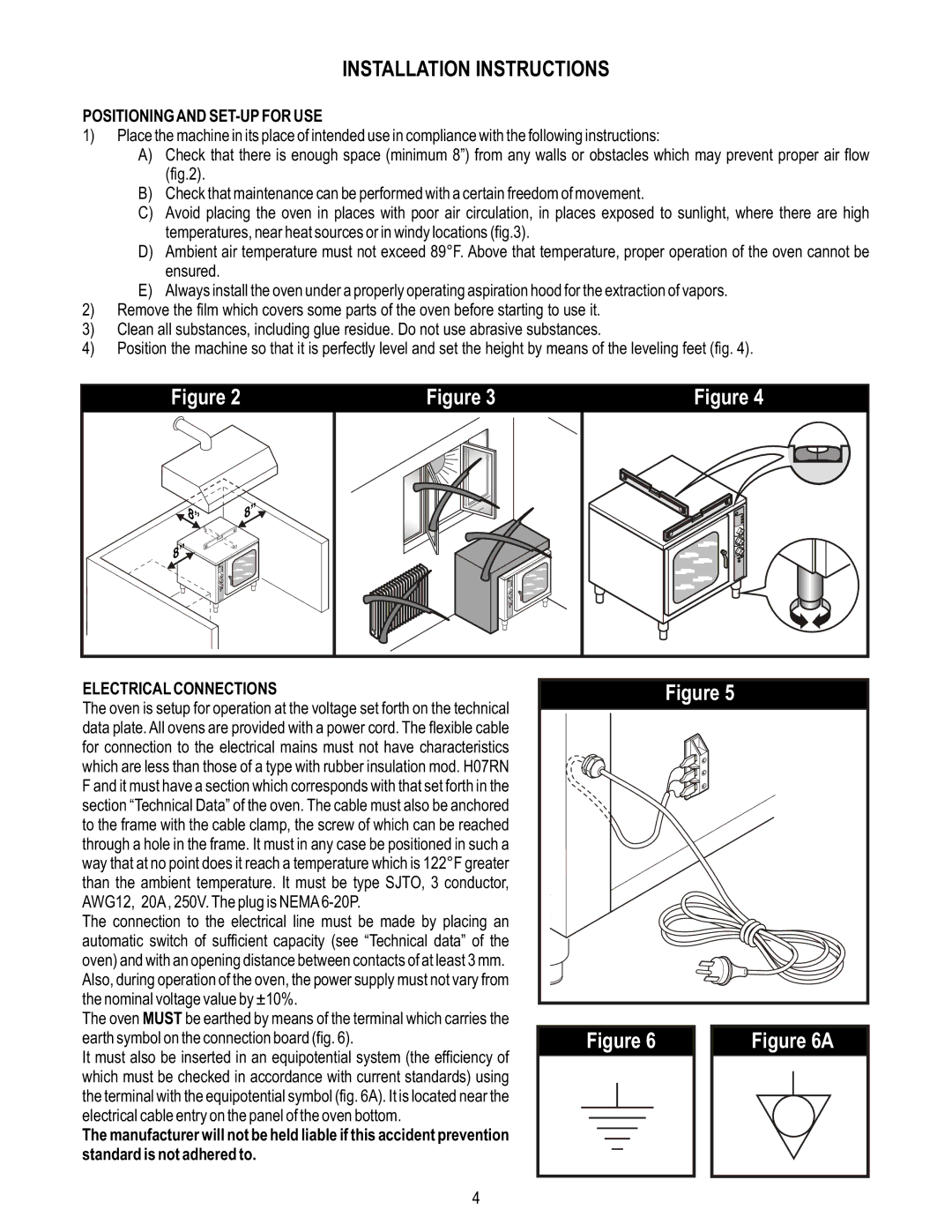
A)Check that there is enough space (minimum 8”) from any walls or obstacles which may prevent proper air flow (fig.2).
B)Check that maintenance can be performed with a certain freedom of movement.
C)Avoid placing the oven in places with poor air circulation, in places exposed to sunlight, where there are high temperatures, near heat sources or in windy locations (fig.3).
D)Ambient air temperature must not exceed 89°F. Above that temperature, proper operation of the oven cannot be ensured.
E)Always install the oven under a properly operating aspiration hood for the extraction of vapors.
2)Remove the film which covers some parts of the oven before starting to use it.
3)Clean all substances, including glue residue. Do not use abrasive substances.
4)Position the machine so that it is perfectly level and set the height by means of the leveling feet (fig. 4).
Figure 2 | Figure 3 | Figure 4 |
1 | 8”” |
|
8”” |
|
|
8”” |
|
|
ELECTRICAL CONNECTIONS
The oven is setup for operation at the voltage set forth on the technical data plate. All ovens are provided with a power cord. The flexible cable for connection to the electrical mains must not have characteristics which are less than those of a type with rubber insulation mod. H07RN F and it must have a section which corresponds with that set forth in the section “Technical Data” of the oven. The cable must also be anchored to the frame with the cable clamp, the screw of which can be reached through a hole in the frame. It must in any case be positioned in such a way that at no point does it reach a temperature which is 122°F greater than the ambient temperature. It must be type SJTO, 3 conductor, AWG12, 20A , 250V. The plug is NEMA
The connection to the electrical line must be made by placing an automatic switch of sufficient capacity (see “Technical data” of the oven) and with an opening distance between contacts of at least 3 mm. Also, during operation of the oven, the power supply must not vary from the nominal voltage value by ±10%.
The oven MUST be earthed by means of the terminal which carries the earth symbol on the connection board (fig. 6).
It must also be inserted in an equipotential system (the efficiency of which must be checked in accordance with current standards) using the terminal with the equipotential symbol (fig. 6A). It is located near the electrical cable entry on the panel of the oven bottom.
The manufacturer will not be held liable if this accident prevention
standard is not adhered to.
Figure 5
| Figure 6 |
| Figure 6A | |||||||||||
|
|
|
|
|
|
|
|
|
|
|
|
|
|
|
|
|
|
|
|
|
|
|
|
|
|
|
|
|
|
|
|
|
|
|
|
|
|
|
|
|
|
|
|
|
|
|
|
|
|
|
|
|
|
|
|
|
|
|
|
|
|
|
|
|
|
|
|
|
|
|
|
|
|
|
|
|
|
|
|
|
|
|
|
|
|
|
|
|
|
|
|
|
|
|
|
|
|
|
|
|
|
|
|
|
|
|
|
|
|
|
|
|
|
|
|
|
|
|
|
|
|
|
|
|
|
|
|
|
|
|
|
|
|
|
4