AUTOMATIC SAFETY & CONTROL DEVICES OF OVEN
PROTECTION OF THE AUXILIARY ELECTRICAL CIRCUIT
It is checked by the fuses positioned on a terminal block at the line entry.
PROTECTION OF THE CHAMBER FAN
A remote switch stops the fan motor in the event of a malfunction or overload. It is located behind the oven and must be reset manually. When it cuts in, it stops the motor and shuts off the heating elements.
OVEN CHAMBER SAFETY THERMOSTAT
The safety thermostat disconnects the heating elements if the temperature in the oven chamber is too high (644°F). It must be reset manually. If it activates, technical service must be notified. All components are protected by the following type of fuse: CLASS CC,G 600V 20A.
REPLACEMENT OF SPARE PARTS
Replacement of spare parts must be performed exclusively by qualified and AUTHORIZED personnel. Turn the main switch OFF and unplug the convection oven before carrying out any spare parts replacement.
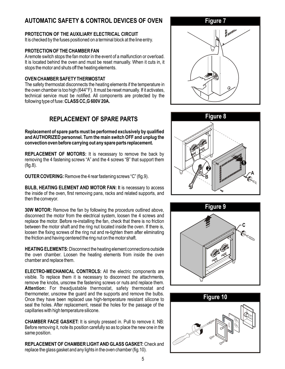
REPLACEMENT OF MOTORS: It is necessary to remove the back by removing the 4 fastening screws “A” and the 4 screws “B” that support them (fig.8).
OUTER COVERING: Remove the 4 rear fastening screws “C” (fig.9).
BULB, HEATING ELEMENT AND MOTOR FAN: It is necessary to access the inside of the oven, first removing pans, racks and related supports, and then the conveyor.
30W MOTOR: Remove the fan by following the procedure outlined above, disconnect the motor from the electrical system, loosen the 4 screws and replace the motor. Before
HEATING ELEMENTS: Disconnect the heating element connections outside the oven chamber. Loosen the heating elements from inside the oven chamber and replace them.
CHAMBER FACE GASKET: It is simply pressed in. Pull to remove it. NB: Before removing it, note its position carefully so as to place the new one in the same position.
REPLACEMENT OF CHAMBER LIGHT AND GLASS GASKET: Check and replace the glass gasket and any lights in the oven chamber (fig.10).
Figure 7
Figure 8
![]()
![]()
![]()
![]()
![]()
![]()
![]()
![]()
![]() 1 2
1 2 ![]()
![]()
![]()
![]()
![]()
![]() A B
A B ![]()
![]()
![]()
![]()
![]()
![]()
![]()
![]()
![]()
Figure 9
![]() C
C
Figure 10
5