Operating Instructions and Parts Manual
PRO1002403, PRO1502403, PRO2002403, PRO100120, PRO150120, and PRO200120
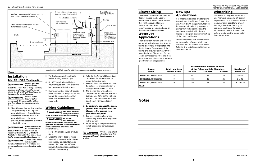
Hartford Loop required if Blower is more than 25 feet away from pool / spa
Alternate location for check valve if Harford Loop is used
Grade
12 inch minimum![]()
5 Foot minimum from water (use
Conduit box and cover
24 inches above surrounding grade / 12 inch minimum above water
Orient blower housing as shown
Bracket
Wall or post
Check valve (location when NOT using a Hartford Loop)
![]() Rigid PVC pipe
Rigid PVC pipe
Blower Sizing
The number of holes in the seats and floor of the spa can be used to determine the size of the air blower that will be required for your application. See Chart 1 for recommended blower size based on the number and size of holes.
Water Jet
Applications
The blower can be used to boost the output of hydrotherapy jets. A venturi fitting is normally incorporated into the jet design. The purpose of the fitting is to allow air to mix with the water in the jet. The venturi fittings
New Spa
Applications
It is important to select a water pump that will supply sufficient flow to the jets. Consult with the jet manufacturer for assistance in selecting a pump or pumps that will accommodate the number of jets desired in the spa. Improper sizing can cause overheating of the pump and blower.
Choose the correct size blower based on the number of water jets in your spa (see Chart 1). See the chart below. Refer to the installation guidelines for additional details.
Winterizing
The blower is designed for outdoor use. There are no special
![]() Air flow
Air flow
Mount using rigid PVC pipe. For additional support, use supplied bracket as shown.
Figure 1
can be connected together and then pressurized with air from the blower to greatly increase the jet action.
|
| Recommended Number of Holes |
| ||
Blower | Total Hole Area | at the Following Hole Diameters | Number of | ||
Model | Square Inches | 1/8 Inch | 3/16 Inch | 1/4 Inch | Water Jets |
Installation
Guidelines (Continued)
Do not glue the blower to the
supply line. Glue fumes can potentially cause an explosion when the blower starts. Install a 1/4”
Do not install blower below
water level. Blower must be at least one foot above the maximum water level.
4.Mount blower in a vertical position using vertical rigid PVC pipe as shown in Figure 1. For additional support use supplied bracket as shown in Figure 1. For warm climates, try to locate the blower in a shaded location.
If the blower is to be installed more
than 25 ft from the spa, it will be necessary to install a loop that is 1 foot above the water line and as close to the spa as possible (See Figure 1).
A loop and a check valve must be
installed at least one foot above the water level when supercharging water jets.
5.Verify plumbing is free of leaks before adding water to spa.
6.Do NOT install adjustable jets. Adjustable jets can cause excessive back pressure within the unit.
7.Hydrotherapy jets naturally aerate when installed correctly. Do not use blower to supplement aeration when jets have been installed incorrectly.
Wiring Guidelines
Failure to observe wiring instructions,
could result in death or serious injury.
All wiring and electrical
connections must be performed by a qualified electrician. Installations must be in accordance with local and national codes.
1.For electrical ratings, see product decal.
2.Check the line voltage to make certain it is correct for the blower being used. Do not attempt to connect 240 VAC to a
3.Refer to the National Electric Code Guidelines for wire size and to prevent electric shock.
4.Refer to the National Electric Code Guidelines for proper selection of wiring conduit and strain relief.
5.The blower
6.Be certain to connect the green ground wire supplied with the blower to the ground from your electrical panel.
7.Connect remaining line wires individually to the remaining wires in the blower.
8.When wiring is complete carefully install gasket and conduit cover plate.
Overheating, short- circuiting and fire
damage will result from inadequate wiring.
PRO100120, PRO1002403 | 1.0 | 76 | 35 | 20 | 4 to 9 |
|
PRO150120, PRO1502403 | 1.4 | 100 | 46 | 26 | 9 to 13 |
|
|
|
|
|
|
|
|
PRO200120, PRO2002403 | 1.8 | 150 | 68 | 38 | 14 or more |
|
|
|
|
|
|
|
|
Chart 1 |
|
|
|
|
|
|
Notes
877.278.2797 | www.aquaprosystems.com |
www.aquaprosystems.com | 877.278.2797 |
2 | 3 |