Installation and Wiring
Connect the system wires as follows:
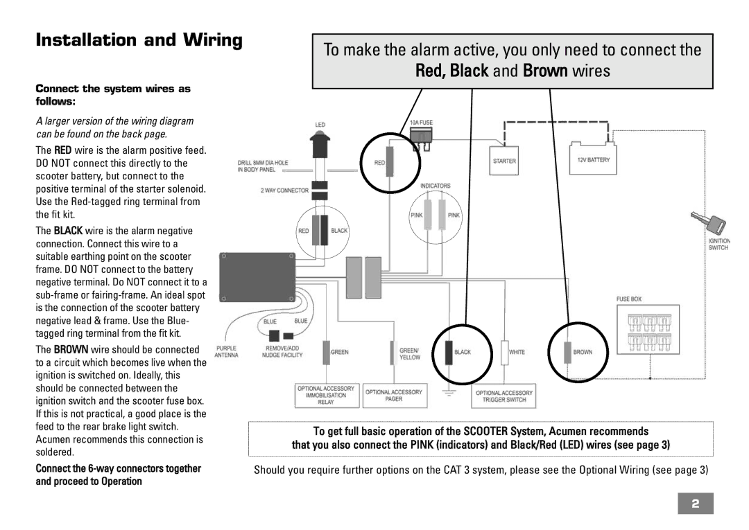
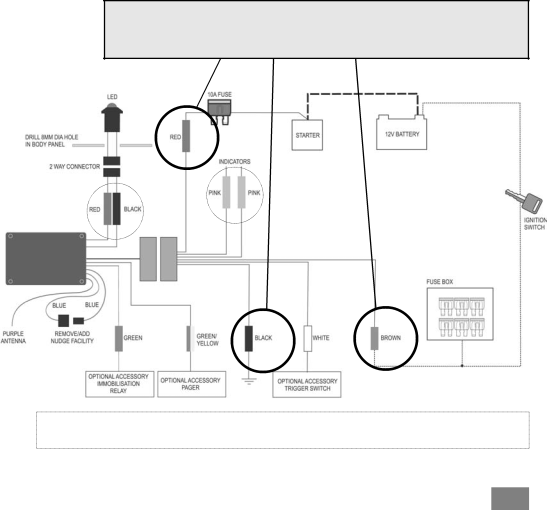
A larger version of the wiring diagram can be found on the back page.
The RED wire is the alarm positive feed. DO NOT connect this directly to the scooter battery, but connect to the positive terminal of the starter solenoid. Use the
The BLACK wire is the alarm negative connection. Connect this wire to a suitable earthing point on the scooter frame. DO NOT connect to the battery negative terminal. Do NOT connect it to a
The BROWN wire should be connected to a circuit which becomes live when the ignition is switched on. Ideally, this should be connected between the ignition switch and the scooter fuse box. If this is not practical, a good place is the feed to the rear brake light switch. Acumen recommends this connection is soldered.
Connect the
To make the alarm active, you only need to connect the
Red, Black and Brown wires
To get full basic operation of the SCOOTER System, Acumen recommends
that you also connect the PINK (indicators) and Black/Red (LED) wires (see page 3)
Should you require further options on the CAT 3 system, please see the Optional Wiring (see page 3)
2