CONTROLS AND OPERATION
A | – | + |
B |
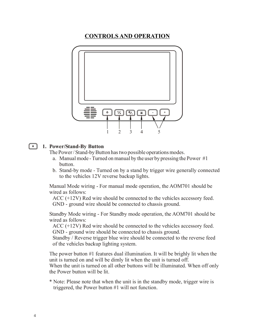
1 | 2 | 3 | 4 | 5 |
1.Power/Stand-By Button
The Power /
a.Manual mode - Turned on manual by the user by pressing the Power #1 button.
b.
Manual Mode wiring - For manual mode operation, the AOM701 should be wired as follows:
ACC (+12V) Red wire should be connected to the vehicles accessory feed. GND - ground wire should be connected to chassis ground.
Standby Mode wiring - For Standby mode operation, the AOM701 should be wired as follows:
ACC (+12V) Red wire should be connected to the vehicles accessory feed. GND - ground wire should be connected to chassis ground.
Standby / Reverse trigger blue wire should be connected to the reverse feed of the vehicles backup lighting system.
The power button #1 features dual illumination. It will be brighly lit when the unit is turned on and will be dimly lit when the unit is turned off.
When the unit is turned on all other buttons will be illuminated. When off only the Power button will be lit.
*Note: Please note that when the unit is in the standby mode, trigger wire is triggered, the Power button #1 will not function.
4