Audio / Video connections
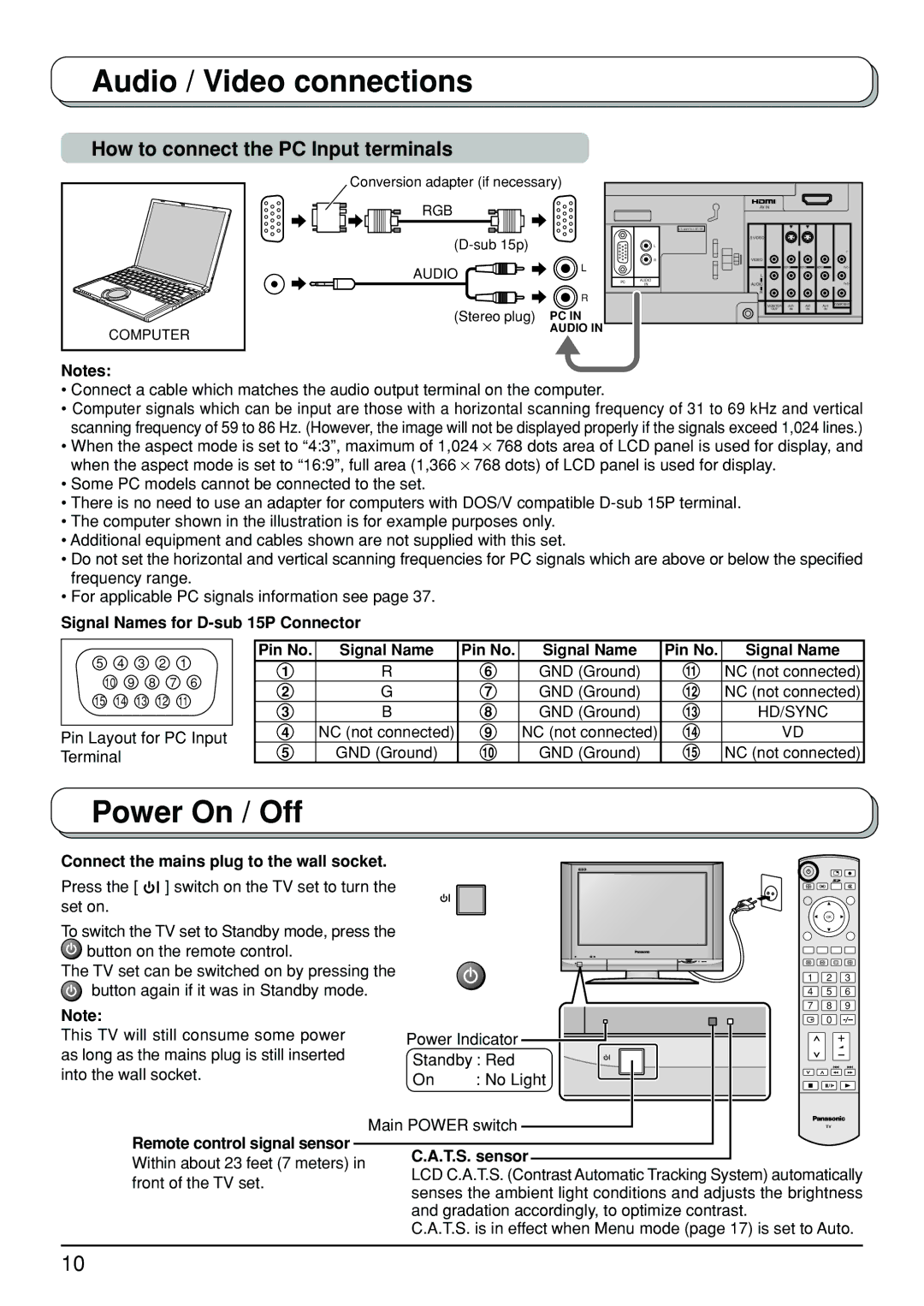
How to connect the PC Input terminals
COMPUTER |
Conversion adapter (if necessary) |
|
|
|
|
|
| |
RGB |
|
| AV IN |
|
|
|
|
|
|
|
|
|
|
| |
|
|
| U. S. patent No.4, 907, 093. |
|
|
|
|
|
| S VIDEO |
|
|
|
| |
| L |
|
|
|
|
| |
|
|
|
|
|
| Y | |
|
| R | VIDEO |
|
|
|
|
AUDIO | L |
|
| MONO | MONO | MONO | PB/CB |
|
|
|
|
|
| ||
|
| L |
|
|
|
| |
PC | AUDIO |
|
|
|
|
| |
|
| IN | AUDIO |
|
|
| PR/CR |
| R |
| R |
|
|
|
|
|
|
|
|
|
| COMPONENT | |
|
|
| MONITOR | AV1 | AV2 | AV4 | |
(Stereo plug) | PC IN |
| OUT | IN | IN | IN |
|
|
|
|
|
|
| ||
| AUDIO IN |
|
|
|
|
|
|
Notes:
•Connect a cable which matches the audio output terminal on the computer.
•Computer signals which can be input are those with a horizontal scanning frequency of 31 to 69 kHz and vertical scanning frequency of 59 to 86 Hz. (However, the image will not be displayed properly if the signals exceed 1,024 lines.)
•When the aspect mode is set to “4:3”, maximum of 1,024 ⋅ 768 dots area of LCD panel is used for display, and when the aspect mode is set to “16:9”, full area (1,366 ⋅ 768 dots) of LCD panel is used for display.
•Some PC models cannot be connected to the set.
•There is no need to use an adapter for computers with DOS/V compatible
•The computer shown in the illustration is for example purposes only.
•Additional equipment and cables shown are not supplied with this set.
•Do not set the horizontal and vertical scanning frequencies for PC signals which are above or below the specified frequency range.
•For applicable PC signals information see page 37.
Signal Names for
5 4 3 2 1
10 | 9 | 8 | 7 | 6 | |
15 | 14 | 13 | 12 |
| 11 |
Pin Layout for PC Input Terminal
Pin No. | Signal Name | Pin No. | Signal Name | Pin No. | Signal Name |
1 | R | 6 | GND (Ground) | 11 | NC (not connected) |
2 | G | 7 | GND (Ground) | 12 | NC (not connected) |
3 | B | 8 | GND (Ground) | 13 | HD/SYNC |
4 | NC (not connected) | 9 | NC (not connected) | 14 | VD |
5 | GND (Ground) | 10 | GND (Ground) | 15 | NC (not connected) |
Power On / Off
Connect the mains plug to the wall socket.
Press the [ ![]() ] switch on the TV set to turn the set on.
] switch on the TV set to turn the set on.
|
|
| OK |
| |
To switch the TV set to Standby mode, press the |
|
|
|
| |
button on the remote control. |
|
|
|
| |
The TV set can be switched on by pressing the |
| 1 | 2 | 3 | |
button again if it was in Standby mode. |
| ||||
| 4 | 5 | 6 | ||
Note: |
| 7 | 8 | 9 | |
|
| 0 |
| ||
This TV will still consume some power | Power Indicator |
|
| ||
as long as the mains plug is still inserted | Standby : Red |
|
| ||
into the wall socket. |
|
| |||
On | : No Light |
|
| ||
|
|
| |||
Main POWER switch | TV |
| |||
Remote control signal sensor | C.A.T.S. sensor |
|
| ||
Within about 23 feet (7 meters) in |
|
| |||
LCD C.A.T.S. (Contrast Automatic Tracking System) automatically | |||||
front of the TV set. | |||||
senses the ambient light conditions and adjusts the brightness | |||||
| |||||
| and gradation accordingly, to optimize contrast. |
|
| ||
| C.A.T.S. is in effect when Menu mode (page 17) is set to Auto. | ||||
10