LED Indicators on the Switch
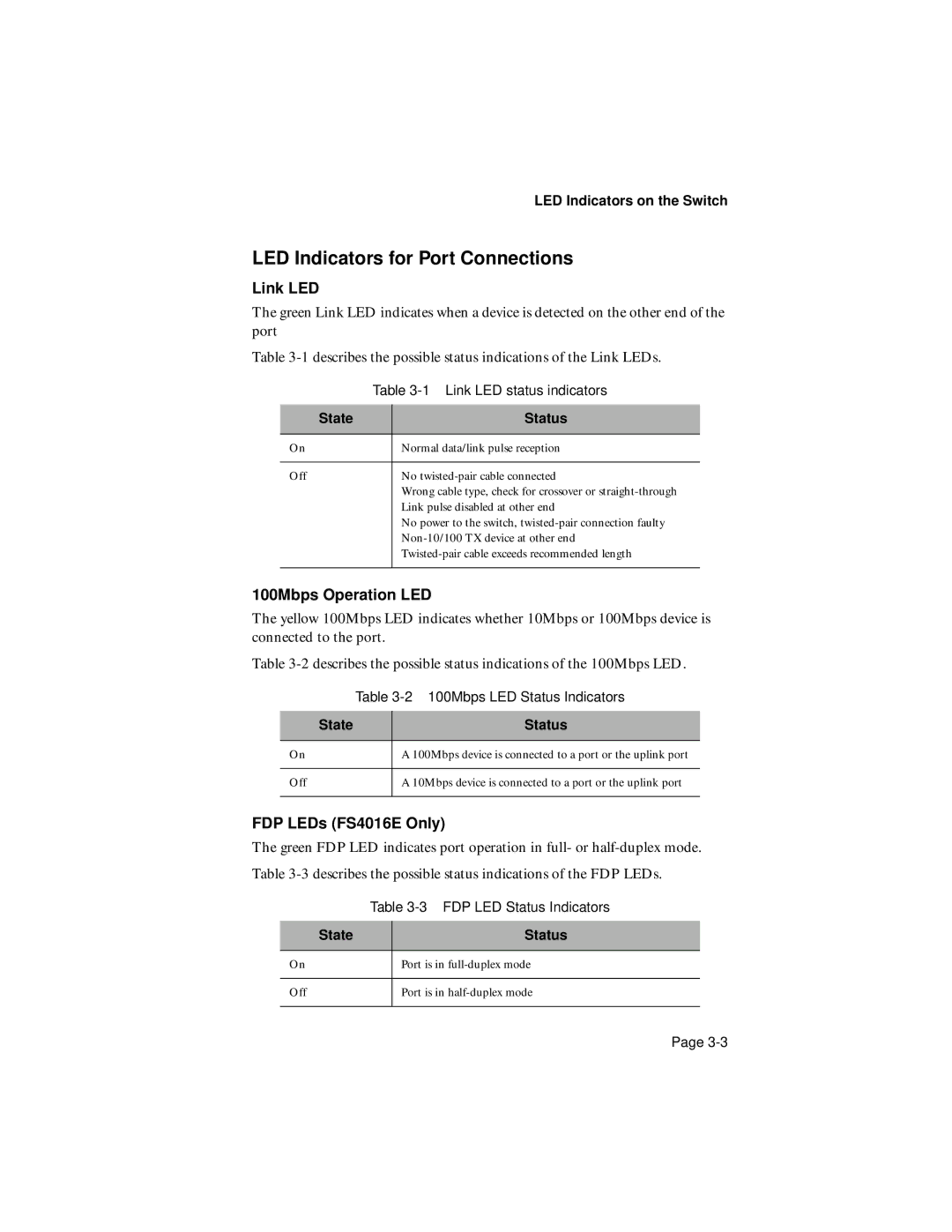
LED Indicators for Port Connections
Link LED
The green Link LED indicates when a device is detected on the other end of the port
Table
| Table | |
|
|
|
State |
| Status |
|
|
|
On |
| Normal data/link pulse reception |
|
|
|
Off |
| No |
|
| Wrong cable type, check for crossover or |
|
| Link pulse disabled at other end |
|
| No power to the switch, |
|
| |
|
| |
|
|
|
100Mbps Operation LED
The yellow 100Mbps LED indicates whether 10Mbps or 100Mbps device is connected to the port.
Table
| Table | |
|
|
|
State |
| Status |
|
|
|
On |
| A 100Mbps device is connected to a port or the uplink port |
|
|
|
Off |
| A 10Mbps device is connected to a port or the uplink port |
|
|
|
FDP LEDs (FS4016E Only)
The green FDP LED indicates port operation in full- or
Table
State
Status
On
Port is in
Off
Port is in
Page