English
2
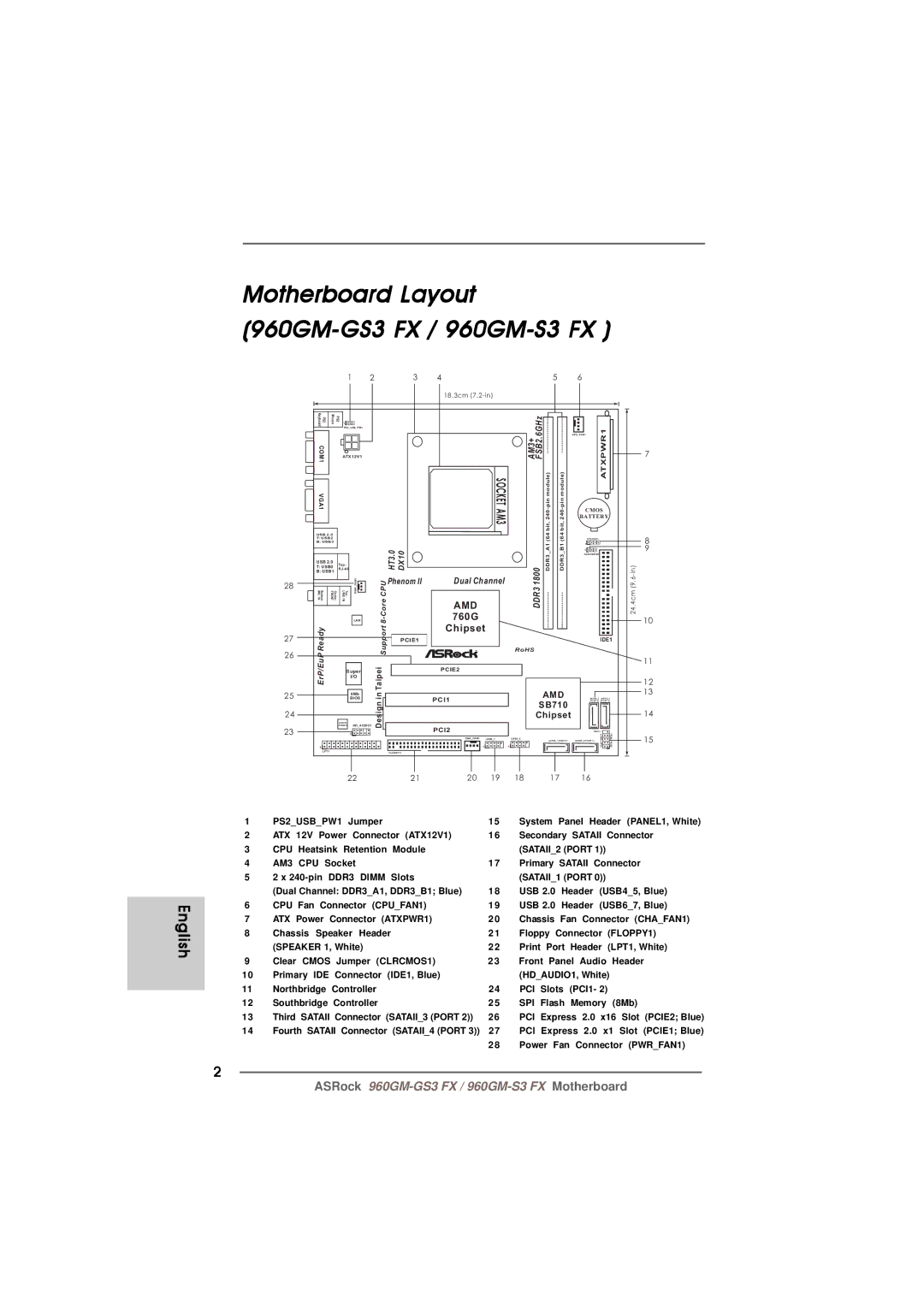
Motherboard Layout
|
|
| |||||||||||||||
|
|
|
| 1 | 2 |
|
| 3 | 4 |
|
|
| 5 | 6 |
|
|
|
|
|
|
|
|
|
|
|
| 18.3cm |
|
|
|
|
|
|
| |
| Keyboard PS2 | Mouse | 1 |
|
|
|
|
|
| AM3+ FSB2.6GHz |
|
|
|
|
|
| |
|
|
|
|
|
|
|
|
|
|
|
|
|
| ||||
|
| PS2_USB_PW1 |
|
|
|
|
|
|
|
|
|
|
| ||||
|
|
|
|
|
|
|
|
|
|
| CPU_FAN1 |
|
|
| |||
|
| ATX12V1 |
|
|
|
|
|
|
|
|
|
| 7 | ||||
| COM1 | PS2 |
|
|
|
|
|
| module)pin |
|
| ATXPWR1 |
|
| |||
|
|
|
|
|
|
| FSB800 |
|
|
| |||||||
| VGA1 |
|
|
|
|
|
|
|
| AM3SOCKET |
| bit,240- | module)bit,240pin- | CMOS |
|
| |
|
|
|
|
|
|
|
|
|
| BATTERY |
|
| |||||
|
|
|
|
|
|
|
|
|
|
|
|
|
| ||||
| USB 2.0 |
|
|
|
|
|
|
|
|
| (64 | (64 |
|
|
|
| |
| T: USB2 |
|
|
|
|
|
|
|
|
| SPEAKER1 |
|
| 8 | |||
| B: USB3 |
|
|
|
|
|
|
|
|
| A1 | B1 | 1 |
|
| ||
|
|
|
|
|
|
|
|
|
|
|
|
|
| ||||
|
|
|
|
|
|
| HT3.0 | DX10 |
|
|
| 1 |
|
| 9 | ||
|
|
|
|
|
|
|
|
|
| CLRCMOS1 |
|
|
| ||||
| USB 2.0 |
| Top: |
|
|
|
|
|
|
|
|
| |||||
| T: USB0 |
|
|
|
|
|
|
|
|
|
| ||||||
|
|
|
|
|
|
|
|
|
|
| |||||||
| B: USB1 |
|
|
|
|
|
|
|
|
|
| ||||||
|
|
|
|
|
|
|
|
| DDR31800 | DDR3 | DDR3 |
|
|
| 24.4cm (9.in)6- | ||
28 |
|
|
|
| PWR FAN1 | CoreCPU | Phenom II | Dual Channel |
|
|
| ||||||
MIC Bottom: IN | FRONT | Center: | LINE Top: IN |
|
|
|
|
|
|
| |||||||
|
|
| AMD |
|
|
|
| ||||||||||
|
|
| 760G |
|
|
|
| ||||||||||
|
|
|
|
| LAN | 8- |
|
|
|
|
|
|
|
|
| 10 | |
|
|
|
|
|
|
|
| Chipset |
|
|
|
|
|
|
| ||
| Ready |
|
|
|
| Support |
|
|
|
|
|
|
|
|
|
| |
27 |
|
|
|
|
| PCIE1 |
|
|
|
|
|
| IDE1 |
| |||
26 |
|
|
|
|
|
|
|
| RoHS |
|
|
|
|
|
| ||
|
|
|
|
|
|
|
|
|
|
|
|
|
|
| |||
ErP/EuP |
|
|
|
|
|
|
|
|
|
|
|
|
|
|
| 11 | |
|
|
|
|
| Taipei |
|
|
|
|
|
|
|
|
|
| ||
|
|
| Super |
|
| PCIE2 |
|
|
|
|
|
|
|
| |||
|
|
| I/O |
|
|
|
|
|
|
|
|
|
| 12 | |||
|
|
|
|
|
|
|
|
|
|
|
|
|
|
| |||
|
|
|
|
|
|
|
|
|
|
|
|
|
|
| 13 | ||
25 |
|
|
| 8Mb | in |
|
|
|
|
| AMD |
|
|
| |||
|
|
| BIOS |
|
| PCI1 |
|
| SATAII_3 SATAII_4 |
|
| ||||||
|
|
|
|
|
| Design |
|
|
| SB710 | (PORT 2) | (PORT 3) |
|
| |||
|
|
|
|
|
|
|
|
|
|
|
|
|
| ||||
24 |
|
|
|
|
|
|
|
|
| Chipset |
|
|
| 14 | |||
|
|
|
| AUDIO |
|
|
|
|
|
|
|
|
|
|
|
| |
|
|
|
| CODEC | HD_AUDIO1 |
|
| PCI2 |
|
|
|
|
|
|
|
| |
23 |
|
|
| 1 |
|
|
|
|
|
|
|
| PANEL 1 | HDLED RESET |
| ||
|
|
|
|
|
|
|
|
|
|
|
|
| PLED PWRBTN | 15 | |||
|
|
|
|
|
|
|
|
| CHA_FAN1 | USB6_7 | USB4_5 | SATAII_1 (PORT 0) | SATAII_2 (PORT 1) | ||||
|
|
|
|
|
|
|
|
|
|
|
|
|
|
| |||
| 1 |
|
|
|
|
|
|
| 1 |
| 1 |
|
|
|
| ||
|
|
|
|
|
|
|
|
|
|
|
|
|
| 1 |
|
| |
| LPT1 |
|
|
|
|
| FLOPPY1 |
|
|
|
|
|
|
|
|
| |
|
|
|
| 22 |
|
| 21 | 20 | 19 | 18 |
| 17 | 16 |
|
|
| |
1 | PS2_USB_PW1 Jumper |
| 15 | System Panel Header (PANEL1, White) | ||||
2 | ATX 12V Power Connector (ATX12V1) | 16 | Secondary SATAII Connector | |||||
3 | CPU | Heatsink Retention | Module |
| (SATAII_2 (PORT 1)) | |||
4 | AM3 | CPU | Socket |
| 17 | Primary SATAII Connector | ||
5 | 2 x | DDR3 DIMM | Slots |
| (SATAII_1 (PORT 0)) | |||
| (Dual Channel: DDR3_A1, DDR3_B1; Blue) | 18 | USB 2.0 | Header | (USB4_5, Blue) | |||
6 | CPU Fan Connector (CPU_FAN1) | 19 | USB 2.0 | Header | (USB6_7, Blue) | |||
7 | ATX Power Connector (ATXPWR1) | 20 | Chassis Fan Connector (CHA_FAN1) | |||||
8 | Chassis Speaker Header |
| 21 | Floppy Connector (FLOPPY1) | ||||
| (SPEAKER 1, White) |
| 22 | Print Port Header (LPT1, White) | ||||
9 | Clear CMOS Jumper (CLRCMOS1) | 23 | Front Panel Audio Header | |||||
10 | Primary IDE Connector (IDE1, Blue) |
| (HD_AUDIO1, White) | |||||
11 | Northbridge Controller |
| 24 | PCI Slots (PCI1- 2) | ||||
12 | Southbridge Controller |
| 25 | SPI Flash Memory (8Mb) | ||||
13 | Third SATAII Connector (SATAII_3 (PORT 2)) | 26 | PCI Express 2.0 x16 Slot (PCIE2; Blue) | |||||
14 | Fourth SATAII Connector (SATAII_4 (PORT 3)) | 27 | PCI Express 2.0 x1 Slot (PCIE1; Blue) | |||||
|
|
|
|
| 28 | Power Fan Connector (PWR_FAN1) | ||
ASRock