English
Copyright Notice
Disclaimer
Motherboard Layout
Off No Link Blinking Data Activity
LAN Port LED Indications
Introduction
Package Contents
Specifications
Bios Feature
Connector
Support CD
Hardware
English
ASRock Instant Boot
English Unique Features
ASRock OC Tuner
ASRock Intelligent Energy Saver
ASRock APP Charger
ASRock OC DNA
ASRock XFast USB
ASRock XFast LAN
ASRock XFast RAM
Pre-installation Precautions
Installation
Installation of CPU Fan and Heatsink English
CPU Installation
Dual Channel Memory Configurations
Installation of Memory Modules Dimm
Notch break Break
Installing a Dimm
Pcie Slots
Installing an expansion card
Expansion Slots PCI and PCI Express Slots
Jumper
Jumpers Setup
Description
Clear Cmos Jumper
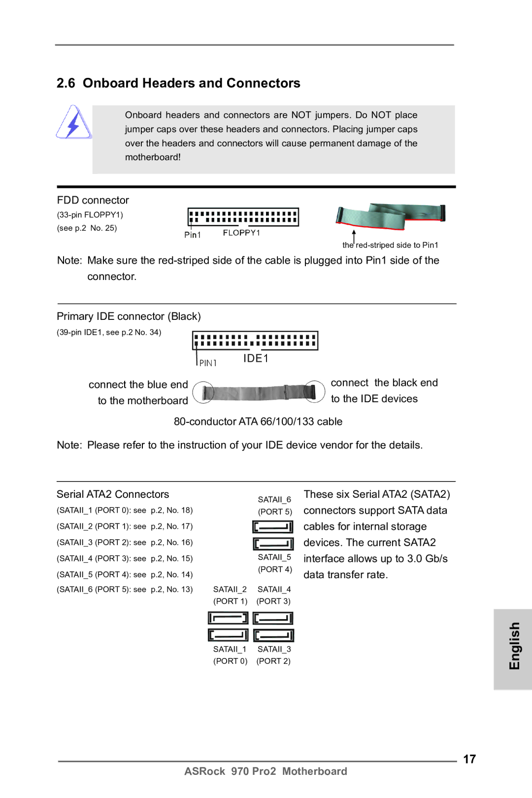
FDD connector
Onboard Headers and Connectors
Primary IDE connector Black
Connect the black end
Serial ATA Sata Data Cable
Internal Audio Connectors
USB 2.0 Headers
Infrared Module Header
Several system front panel
System Panel Header
Match the black wire to
To the fan connectors
CPU Fan Connectors
Cable to the connector
ATX 12V Power Connector
ATX Power Connector
Installing Windows XP / XP 64-bit Without RAID Functions
English Driver Installation Guide
\ RAID Installation Guide
Install Windows XP / XP 64-bit OS on your system
Untied Overclocking Technology
Bios Information
ASRock 970 Pro2 지원 CD 시리얼 ATA Sata 데이터 케이블 2 개 선택 사양 차폐 1 개
제품소개
Socket AM3+ 프로세서에 대한 지원
플랫폼 ATX 폼 팩터 12.0 x 7.5, 30.5 x 19.1 cm 완전 고체 축전지 디자인
Socket AM3 프로세서에 대한 지원 AMD PhenomTM II
X4 / X3 / X2 920/940 제외 / Athlon II X4 / X3
ErP/EuP 지원 ErP/EuP 지원 전원 공급기가 요구됨
Bios
Cmos 초기화
점퍼 셋팅
참고 케이블의 빨간색 줄무늬가 있는 쪽을 커넥터의 1 번 핀에 맞추어 연결하십시오 IDE 콘넥터 1 검정
콘넥터 FDD 콘넥터
개의 시리얼 ATA2 장
SATA2 커넥터는 내부 저장
USB 2.0 헤더
시리얼 Atasata 데이터 케이블
적외선 모듈 헤더
것입니다 콘넥터는 오디오 장치를 편리하게 조절하고 연결할 수 있는 전면 오디오 인터페이스
것입니다
시스템 콘넥터 콘넥터는 시스템 전면 패
널기능을 지원하기 위한
연결하십시오
새시 스피커 헤더
전원 LED 헤더
케이블을 팬 커넥터에 연결하 고 접지 핀에는 검은색 전선을 연결하십시오 CPU 팬 커넥터
ATX 12V 파워 콘넥터 ATX 12V 플러그가 달린
ATX 전원 헤더 ATX 전원 공급기를 이 헤더에
전원공급장치를 이 커넥터에
연결해야 충분한 전력을
시스템 바이오스 정보 소프트웨어 지원 CD 정보
I/O パネルシールド
ATX フォームファクター 12.0-in x 7.5-in, 30.5 cm x 19.1 cm
ASRock 970 Pro2 サポート CD
Socket AM3+ プロセッサのサポート
X 7.5-in, 30.5 cm x 19.1 cm
Socket AM3 プロセッサのサポート AMD PhenomTM
X6 / X4 / X3 / X2920 / 940 を除く / Athlon
Smbios 2.3.1 サポート
Bios 関連機能 8Mb AMI Legal Bios
RJ-45 LAN ポート x
SATA2 3.0Gb/ 秒コネクタが、RAID RAID 0, RAID
ジャンパ設定
オンボードのヘッダとコネクタ類
赤外線モジュールコネクタ
Ground GND を Ground GND に接続しま す。
シャーシスピーカーヘッダ
ATX パワーコネクタ ATX 電源コネクタを接続します。
. ソフトウェア サポート CD 情報
兩條 Serial Atasata 數據線 選配 一塊 I/O 擋板
主板簡介
支持異步超頻技術
全固態電容設計 處理器
芯片組
系統內存 支持雙通道內存技術
連接頭
高保真音頻插孔:音頻輸入 / 前置喇叭 / 麥克風
紅外線模塊接頭
電源指示燈連接排針
清除 Cmos
跳線設置
注意 請確保數據線標紅色斑紋的一邊插入連接器第 1 針腳 Pin1 的位置。 IDE 連接頭 黑色
軟驅接頭
藍色端接到主板上
注意 請查閱您的 IDE 驅動器供應商提供的說明書了解詳細資料。
USB 2.0 接口之外,這款
除了位於 I/O 面板的六個默
主板有三組 USB 2.0 接針。
這組 USB 2.0 接針可以支持
系統面板接頭
接頭,並讓黑線與接地的針腳
機箱 , 電源風扇接頭 請將風扇連接線接到這個
相接。
請將 CPU 風扇連接線接到這個
查找支持光盤內 BIN 文件夾下的ASSETUP.EXE,并雙擊它,即可調出主菜單。
主板上的 Flash Memory 存儲了 Bios 設置程序。請再啟動電腦進行開機自檢 Post
器接到這個接頭。
電視 / 投影儀 / 液晶顯示器等
若您慾了解此產品的有毒有害物質或元素的名稱及含量說明,請參照以下表格及說 明。
電子信息產品污染控制標示
ATX 規格 12.0 英吋 x 7.5 英吋 , 30.5 公分 x 19.1 公分
謝謝你採用了華擎 970 Pro2 主機板 , 本主機板由華擎嚴格製造 , 品質可靠 , 穩定性
支援 Socket AM3+ 處理器
12.0 英吋 x 7.5 英吋 , 30.5 公分 x 19.1 公分
X3 / X2920 / 940 除外 / Athlon II X4 / X3
Sempron 處理器 八核心 CPU 就緒 Digi 電源設計 支援高達 140W 的 CPU
紅外線模組接頭
高清晰音效插孔:音效輸入 / 前置喇叭 / 麥克風
電源指示燈接頭
內置音效接頭
跳線設置
注意 請確保數據線標紅色的一邊插入接頭第 1 針腳 Pin1 的位置。 IDE 接頭 黑色
磁碟機接頭
藍色端接到主機板上黑色端接到硬碟驅動器上
線作為內部儲存設置。
主機板有三組 USB 2.0 接
除了位於 I/O 面板的六個
支援兩個 USB 2.0 接口。
這個接頭支援一個選配的模
機箱喇叭接頭
系統面板接頭
重啟鍵等各種連線。
ATX 電源接頭
機箱 , 電源風扇接頭 請將風扇連接線接到這個接
插頭的電源供應器連接到這個
請注意,必需將帶有 ATX
插座,這樣就可以提供充足的
電力。如果不這樣做,就會導
Isi Paket
Penjelasan
Spesifikasi
Penghubung
Ciri-ciri Bios
Penjaga
Sertifikasi