2.9 Onboard Headers and Connectors
Onboard headers and connectors are NOT jumpers. Do NOT place jumper caps over these headers and connectors. Placing jumper caps over the headers and connectors will cause permanent damage of the motherboard!
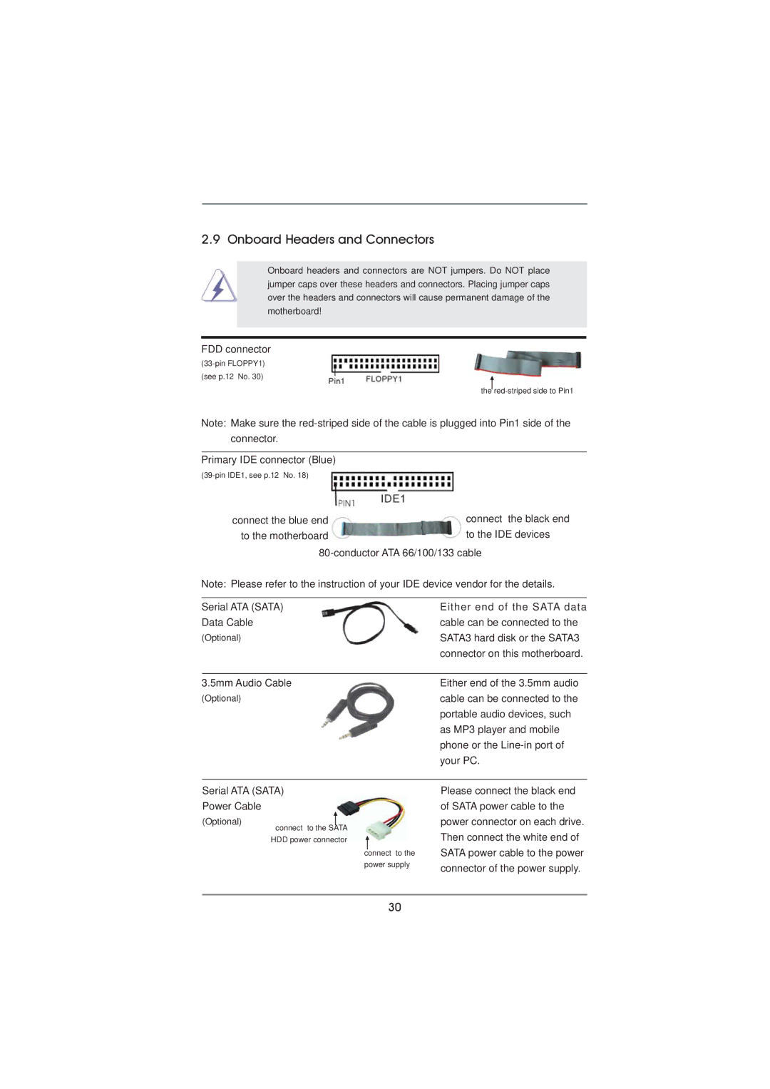
FDD connector
(see p.12 No. 30)
the
Note: Make sure the
connector.
Primary IDE connector (Blue)
connect the blue end | connect the black end |
to the motherboard | to the IDE devices |
Note: Please refer to the instruction of your IDE device vendor for the details.
Serial ATA (SATA) | Either end of the SATA data |
Data Cable | cable can be connected to the |
(Optional) | SATA3 hard disk or the SATA3 |
| connector on this motherboard. |
|
|
3.5mm Audio Cable | Either end of the 3.5mm audio |
(Optional) | cable can be connected to the |
| portable audio devices, such |
| as MP3 player and mobile |
| phone or the |
| your PC. |
Serial ATA (SATA)
Power Cable
(Optional)
connect to the SATA HDD power connector
connect to the power supply
Please connect the black end of SATA power cable to the power connector on each drive. Then connect the white end of SATA power cable to the power connector of the power supply.
30