Getting Started 3
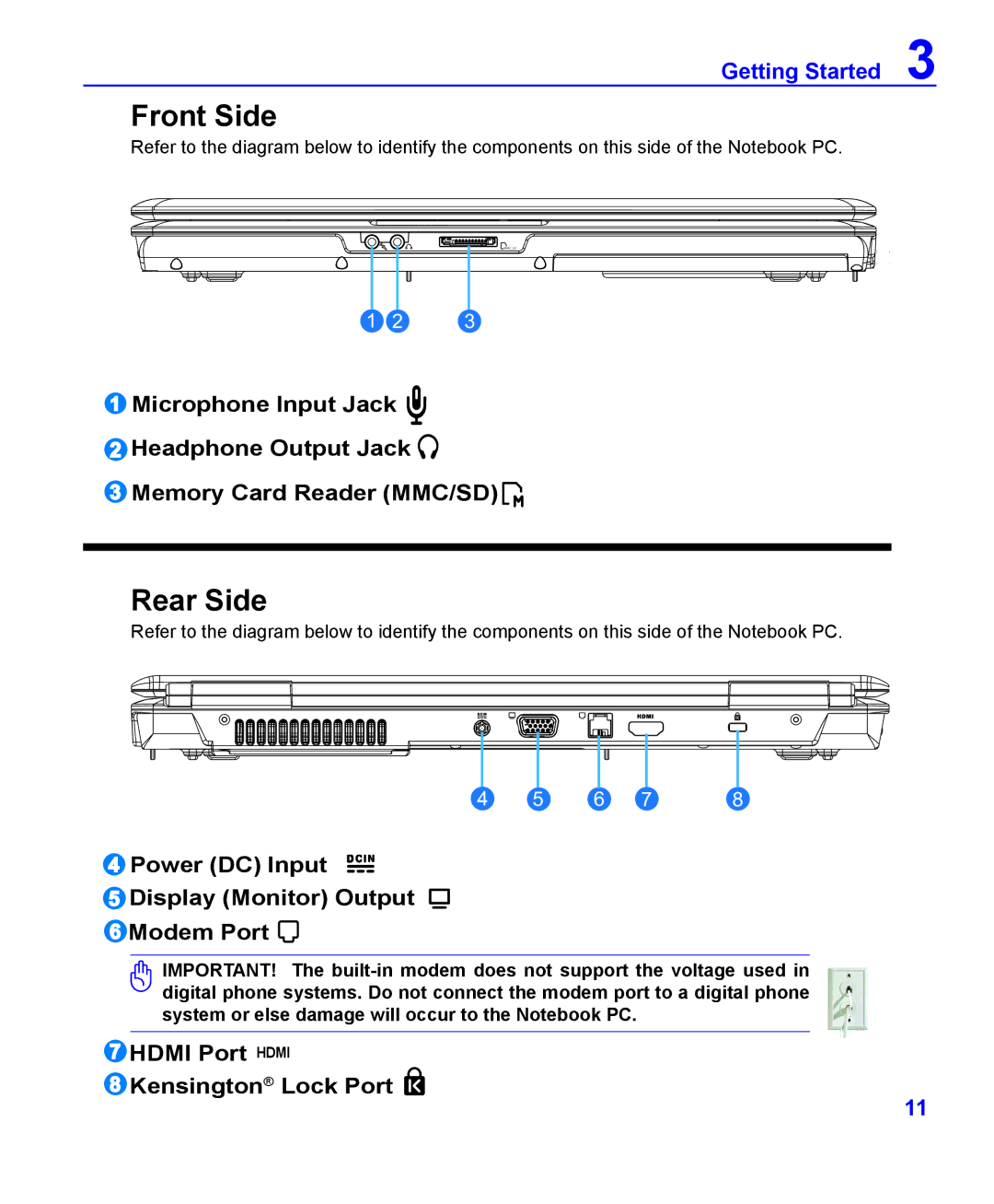
Front Side
Refer to the diagram below to identify the components on this side of the Notebook PC.
MMC .SD
1 | 2 | 3 |
1Microphone Input Jack ![]()
2Headphone Output Jack ![]()
3Memory Card Reader (MMC/SD) ![]()
Rear Side
Refer to the diagram below to identify the components on this side of the Notebook PC.
4 | 5 | 6 | 7 | 8 |
4 Power (DC) Input
5 Display (Monitor) Output
6 Modem Port 
IMPORTANT! The
7 HDMI Port HDMI
8 Kensington® Lock Port
11