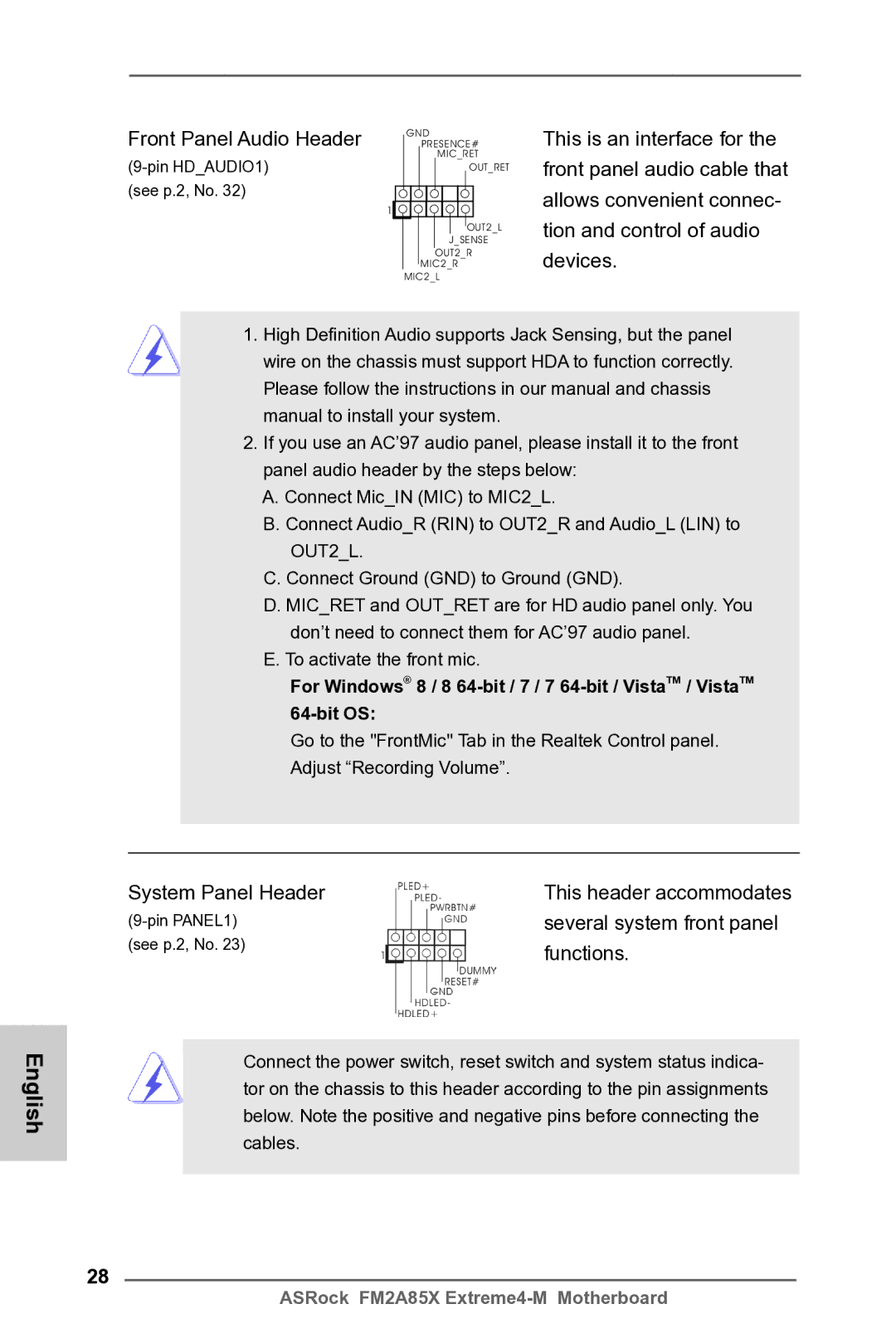
Front Panel Audio Header
(see p.2, No. 32)
GND PRESENCE#
MIC_RET
OUT_RET
1![]()
![]()
![]()
![]()
![]()
![]()
![]()
![]()
![]()
![]()
OUT2_L
J_SENSE
OUT2_R
MIC2_R MIC2_L
This is an interface for the front panel audio cable that allows convenient connec- tion and control of audio devices.
1.High Definition Audio supports Jack Sensing, but the panel wire on the chassis must support HDA to function correctly. Please follow the instructions in our manual and chassis manual to install your system.
2.If you use an AC’97 audio panel, please install it to the front panel audio header by the steps below:
A.Connect Mic_IN (MIC) to MIC2_L.
B.Connect Audio_R (RIN) to OUT2_R and Audio_L (LIN) to OUT2_L.
C.Connect Ground (GND) to Ground (GND).
D.MIC_RET and OUT_RET are for HD audio panel only. You don’t need to connect them for AC’97 audio panel.
E.To activate the front mic.
For Windows® 8 / 8
Go to the "FrontMic" Tab in the Realtek Control panel.
Adjust “Recording Volume”.
System Panel Header | This header accommodates |
several system front panel | |
(see p.2, No. 23) | functions. |
|
English
28
Connect the power switch, reset switch and system status indica- tor on the chassis to this header according to the pin assignments below. Note the positive and negative pins before connecting the cables.
ASRock FM2A85X