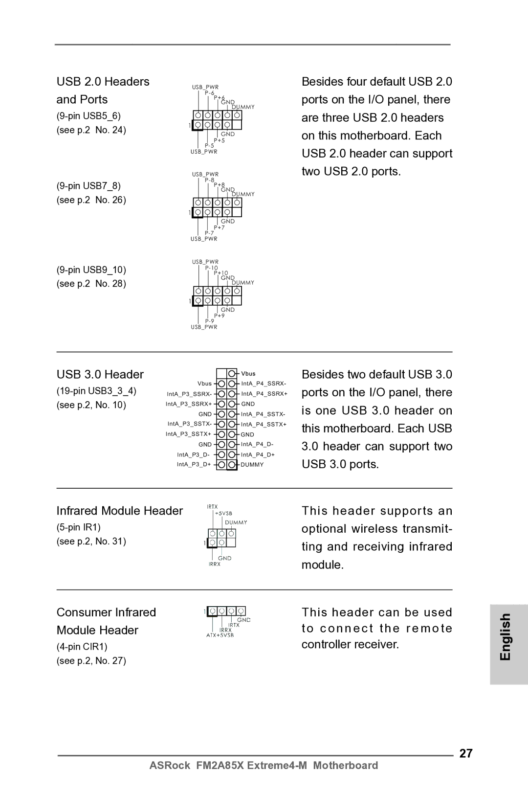
USB 2.0 Headers and Ports
USB_PWR
GND DUMMY
1![]()
![]()
![]()
![]()
![]()
![]()
![]()
![]()
![]()
GND
P+5
USB_PWR
USB_PWR
GND DUMMY
1![]()
![]()
![]()
![]()
![]()
![]()
![]()
![]()
![]()
GND
P+7
USB_PWR
USB_PWR
GND DUMMY
1![]()
![]()
![]()
![]()
![]()
![]()
![]()
![]()
![]()
GND
P+9
USB_PWR
Besides four default USB 2.0 ports on the I/O panel, there are three USB 2.0 headers on this motherboard. Each USB 2.0 header can support two USB 2.0 ports.
USB 3.0 Header
(19-pin USB3_3_4) (see p.2, No. 10)
Vbus
IntA_P3_SSRX-
IntA_P3_SSRX+
GND
IntA_P3_SSTX-
IntA_P3_SSTX+
GND
IntA_P3_D-
IntA_P3_D+
Vbus
IntA_P4_SSRX- IntA_P4_SSRX+
GND
IntA_P4_SSTX- IntA_P4_SSTX+
GND
IntA_P4_D-
IntA_P4_D+
DUMMY
Besides two default USB 3.0 ports on the I/O panel, there is one USB 3.0 header on this motherboard. Each USB
3.0header can support two USB 3.0 ports.
Infrared Module Header | This header supports an |
optional wireless transmit- | |
(see p.2, No. 31) | ting and receiving infrared |
| |
| module. |
|
|
Consumer Infrared | This header can be used |
Module Header | t o c o n n e c t t h e r e m o t e |
controller receiver. | |
(see p.2, No. 27) |
|
27
English
ASRock FM2A85X