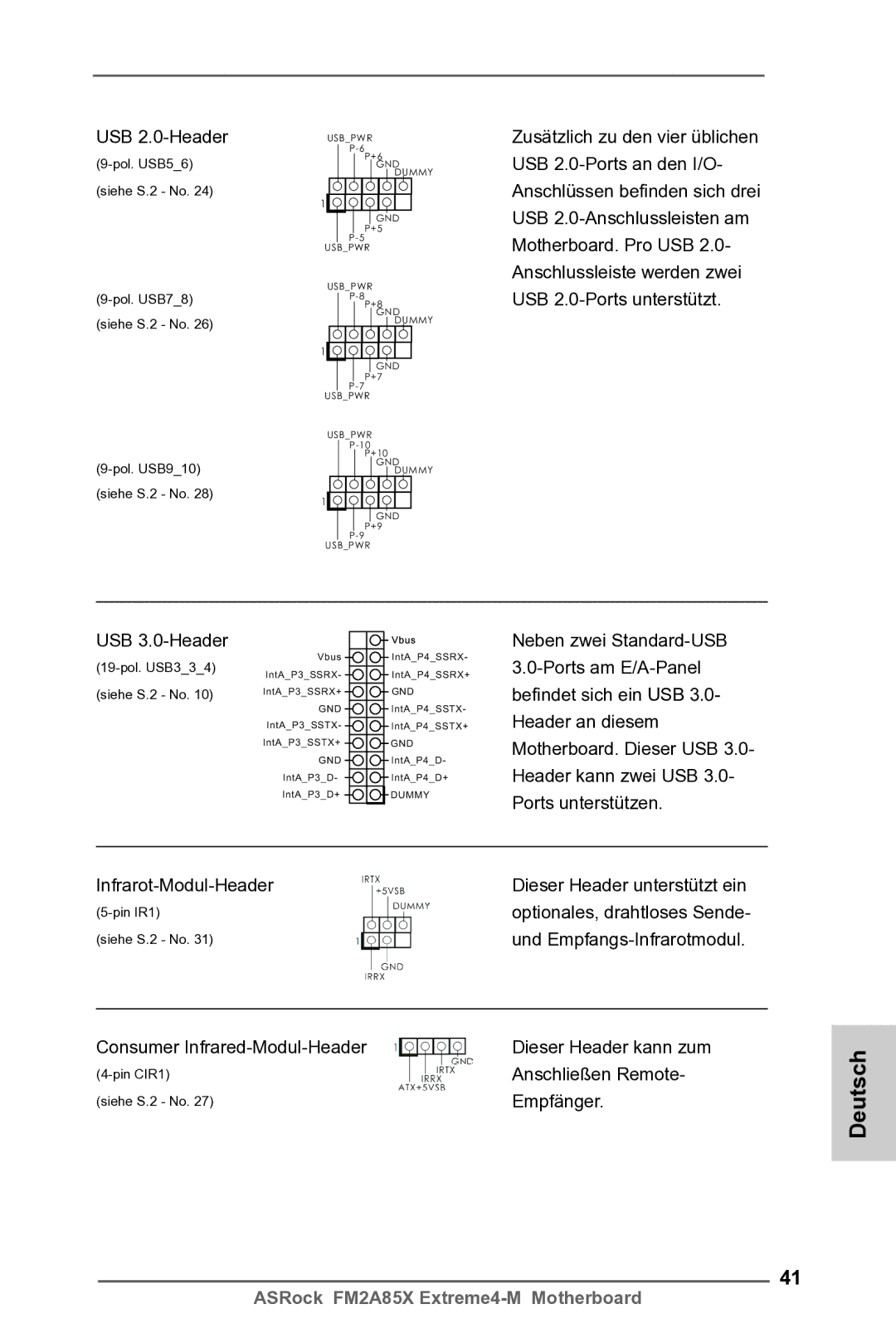
USB | USB_PWR |
| |
P+6 | |
DUMMY | |
| GND |
(siehe S.2 - No. 24) | 1 |
| |
| GND |
| P+5 |
| |
| USB_PWR |
USB_PWR | |
P+8 | |
| |
(siehe S.2 - No. 26) | GND |
DUMMY | |
| 1 |
| GND |
| P+7 |
| |
| USB_PWR |
| USB_PWR |
| |
| P+10 |
GND | |
DUMMY | |
(siehe S.2 - No. 28) | 1 |
| |
| GND |
| P+9 |
| |
| USB_PWR |
Zusätzlich zu den vier üblichen USB
USB
(19-pol. USB3_3_4) (siehe S.2 - No. 10)
Vbus
IntA_P3_SSRX-
IntA_P3_SSRX+
GND
IntA_P3_SSTX-
IntA_P3_SSTX+
GND
IntA_P3_D-
IntA_P3_D+
Vbus
IntA_P4_SSRX- IntA_P4_SSRX+
GND
IntA_P4_SSTX- IntA_P4_SSTX+
GND
IntA_P4_D-
IntA_P4_D+
DUMMY
Neben zwei
Dieser Header unterstützt ein | |
optionales, drahtloses Sende- | |
(siehe S.2 - No. 31) | und |
Consumer | Dieser Header kann zum |
Anschließen Remote- | |
(siehe S.2 - No. 27) | Empfänger. |
Deutsch
41
ASRock FM2A85X