Copyright Notice
Disclaimer
English
Motherboard Layout G41M-VGS3 / G41M-VS3
Panel G41M-VGS3
LAN Port LED Indications
Off No Activity Blinking Data Activity
Panel G41M-VS3
Package Contents
Introduction
Specifications
Unique Feature
Connector
Bios Feature
See Caution
Certifications
FCC, CE, Whql
English
English
Installation
Pre-installation Precautions
CPU Installation
Land CPU
Installation of CPU Fan and Heatsink
English Installation of Memory Modules Dimm
Installing a Dimm
Installing an expansion card
Expansion Slots PCI and PCI Express Slots
Pcie slot
English Jumpers Setup
Jumper Setting Description
Default
FSB1 Jumper
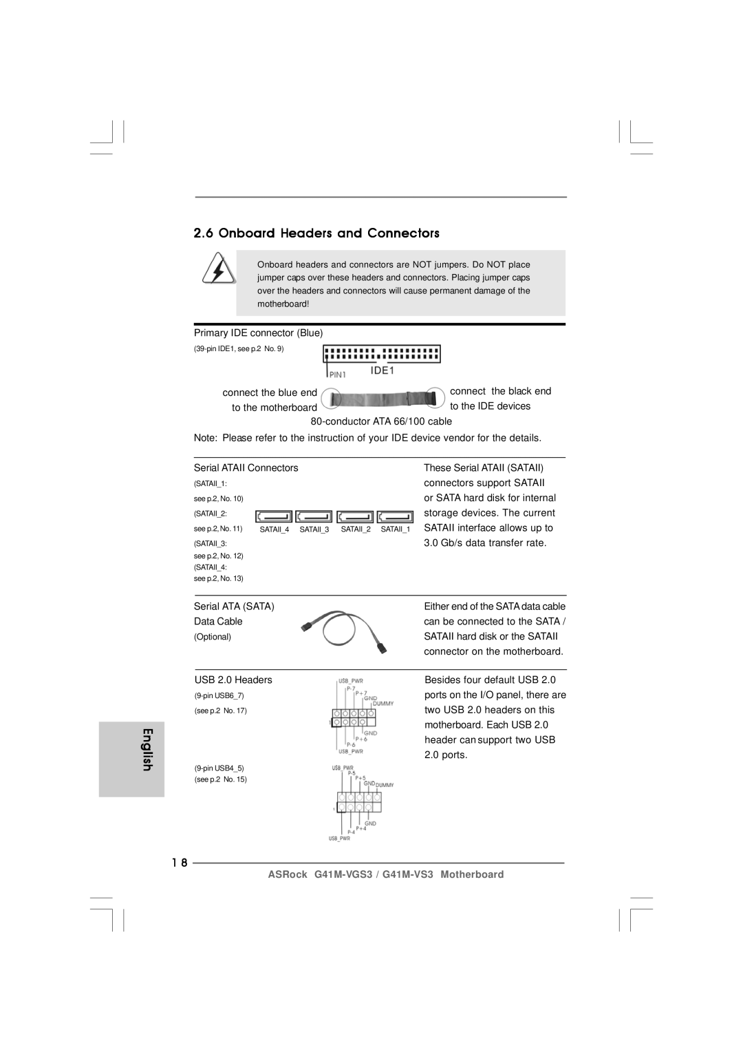
English Onboard Headers and Connectors
Match the black wire to
Chassis Fan Connector Please connect a chassis fan
Cable to this connector
CPU Fan Connector
ATX 12V Connector Please note that it is necessary
ATX Power Connector
Please connect an ATX power supply to this connector
ATX 12V plug to this connector
Driver Installation Guide
Untied Overclocking Technology
Bios Information Software Support CD information
Deutsch
Einführung
Kartoninhalt
Zwei Seriell-ATA- Sata Datenkabel Option Ein I/O Shield
Spezifikationen Deutsch
Support-CD
Einzigartige
Eigenschaft
Zertifizierungen FCC, CE, Whql
Warnung
Deutsch
Deutsch
Einstellung der Jumper
Jumper Einstellun Beschreibung
Integrierte Header und Anschlüsse
Anschlüssen befinden sich
USB 2.0-Header Zusätzlich zu den vier
Üblichen USB 2.0-Ports an den
Am Motherboard. Pro USB
Systemvorderseite
System Panel-Header Dieser Header unterstützt
Mehrere Funktion der
Gehäuselautsprecher-Header Schließen Sie den
BIOS-Information
Contenu du paquet
Français
Français Spécifications
Unique
CD d’assistance
Caractéristique
Surveillance
Ventilateur silencieux d’unité centrale
Tachéomètre ventilateur CPU
Tachéomètre ventilateur châssis
Monitoring de la tension +12V, +5V, +3.3V, Vcore
Français
Français
Ferme Ouvert
Cavalier EUP LAN / EUP Audio
Désactiver EuP Cavalier FSB1
Par défaut
En-têtes et Connecteurs sur Carte
Pratique de périphériques
Câble du port d’impression, qui
Permet le raccordement
’impression
Connecteur et brancher le fil
Connecteur en branchant le fil
Noir sur la broche de terre
En-tête d’alimentation ATX Veuillez connecter l’unité
Informations sur le Bios Informations sur le CD de support
Italiano
Introduzione
Contenuto della confezione
Scheda madre ASRock G41M-VGS3 /G41M-VS3
Specifiche
Supporto
Connettori
CD di
Caratteris
Attenzione
Italiano
Italiano
Setup dei Jumpers
Settaggio del Jumper
Predefinito abilita EuP
Collettori e Connettori su Scheda
All’hard disk Sata / Sataii o al
Cavi dati Serial ATA Sata Entrambe le estremità del cavo
Dati Sata possono collegarsi
Madre
Connettore alimentazione ATX Collegare la sorgente
Connettore
12V ATX a questo connettore
Connettore ATX Necessario collegare una
Alimentazione con spinotto da
Modo che possa fornire
Introducción
Contenido de la caja
Español
Especificación
Característica
Conectores
CD de soport
Única
En conformidad con Microsoft Windows 7 / 7 64 bits
Ventilador silencioso para procesador
Monitor de Voltaje +12V, +5V, +3.3V, Vcore
Vista TM / Vista TM 64 bits / XP / XP 64 bits
Español
Español
Español
Setup de Jumpers
Descripción
FSB1, puente de 3 terminales, consulte la p , Nº
Cabezales y Conectores en Placas
Cabezal USB Además de cuatro puertos
Duro Sata / Sataii o la
Conexión de la placa base
USB 2.0 predeterminados en el
Cabezal de alimentación ATX Conecte la fuente de
Alimentación ATX a su cabezal
Con el enchufe ATX 12V, de
Conector de ATX 12V power Tenga en cuenta que es
Necesario conectar este
Electricidad. De lo contrario no
Bios Información Información de Software Support CD
ASRock G41M-VGS3 / G41M-VS3 Motherboard
ASRock G41M-VGS3 / G41M-VS3 Motherboard
ASRock G41M-VGS3 / G41M-VS3 Motherboard
ASRock G41M-VGS3 / G41M-VS3 Motherboard
ASRock G41M-VGS3 / G41M-VS3 Motherboard
ASRock G41M-VGS3 / G41M-VS3 Motherboard
ASRock G41M-VGS3 / G41M-VS3 Motherboard
Short Open
ASRock G41M-VGS3 / G41M-VS3 Motherboard
SATAII4 SATAII3 SATAII2 SATAII1
ASRock G41M-VGS3 / G41M-VS3 Motherboard
2413 121
ASRock G41M-VGS3 / G41M-VS3 Motherboard
Introdução
Este pacote contém
Português
Especificações
Funcionalidade
Monitor do HW
Sistema
Operacional
Certificações
Português
Português
Português
Português Configuração dos Jumpers
Jumper Configuração
Restaurar FSB1
Conectores
Conector
Entrada/saída, há dois
Cabezal USB Além das quatro portas USB
Por defeito no painel de
Ligações USB 2.0 nesta placa
Neste conector
Conector do painel do sistema
Funções do painel frontal do
Conector do ventilador do
Informações da Bios Informações do CD de Suporte
Türkçe
Türkçe
100
101
102
103
104
105
106
107
108
109
110
111
112
113
114
115
116
117
118
119
120
\ \
122
123
124
125
126
127
128
129
130
131
132
133
134
135
136
137
138
139
140
141
142
143
144
145
146
147
148
149
150
151
152
153
154
155
156
157