Copyright Notice
Disclaimer
English
Motherboard Layout
LAN Port LED Indications
Table for Audio Output Connection
Activity/Link LED
English
WiFi + BT Module
WiFi + BT Module
ASRock Wi-SB Box
ASRock Wi-SB Box
Package Contents
Introduction
Graphics
Wireless LAN
Audio
Rear Panel I/O
Connector
Smart Switch
Bios Feature
USB3.0
Unique Feature
Support CD
See Caution
Hardware
English
English
English
English
Pre-installation Precautions
Screw Holes
CPU Installation
Step Orient the CPU with the IHS Inte
Grated Heat Sink up. Locate Pin1
Two orientation key notches
English
Installation of CPU Fan and Heatsink
English Installation of Memory Modules Dimm
Dual Channel Memory Configuration
Installing a Dimm
Expansion Slots PCI Express Slots
Pcie slots
Pcie Slot Configurations
Installing an expansion card
Requirements
Installing Three SLITM-Ready Graphics Cards
Two Goldfingers
ASRock SLIBridge3S Card
ASRock 3-Way SLI Bridge Card
Installing Four SLITM-Ready Graphics Cards
ASRock SLIBridge Cards An ASRock SLIBridge3S Card
Driver Installation and Setup
For Windows XP / XP 64-bit OS For Slitm mode only
Double-click Nvidia Settings icon on your Windows taskbar
Select Nvidia Control Panel tab
Select Control Panel tab
Follow step a to D on
English
CrossFire Bridge
Installing Three CrossFireXTM-Ready Graphics Cards
CrossFireTM Bridge
Installing Four CrossFireXTM-Ready Graphics Cards
Install the required drivers to your system
For Windows XP OS
For Windows 7 / VistaTM OS
ATI Catalyst Control Center
English
WiFi + BT Module and ASRock Wi-SB Box Installation Guide
English
Surround Display Feature
For Windows XP / XP 64-bit OS
Hdmi port
For Windows 7 / 7 64-bit / VistaTM / VistaTM 64-bit OS
What is HDCP?
Hdcp Function
ASRock Smart Remote Installation Guide
Install Multi-Angle CIR Receiver to the front USB port
Make sure the option CIR Controller is setting at Enabled
Advanced Super IO Configuration CIR Controller Enabled
CIR sensors in different angles
Jumpers Setup
Jumper
Description
Clear Cmos Jumper
Onboard Headers and Connectors
Serial ATA2 Connectors
Serial ATA3 Connectors
Serial ATA Sata Data Cable
Optional wireless transmitting
USB 2.0 Headers
Infrared Module Header
This header supports an
Front Panel Audio Header
System Panel Header
Several system front panel
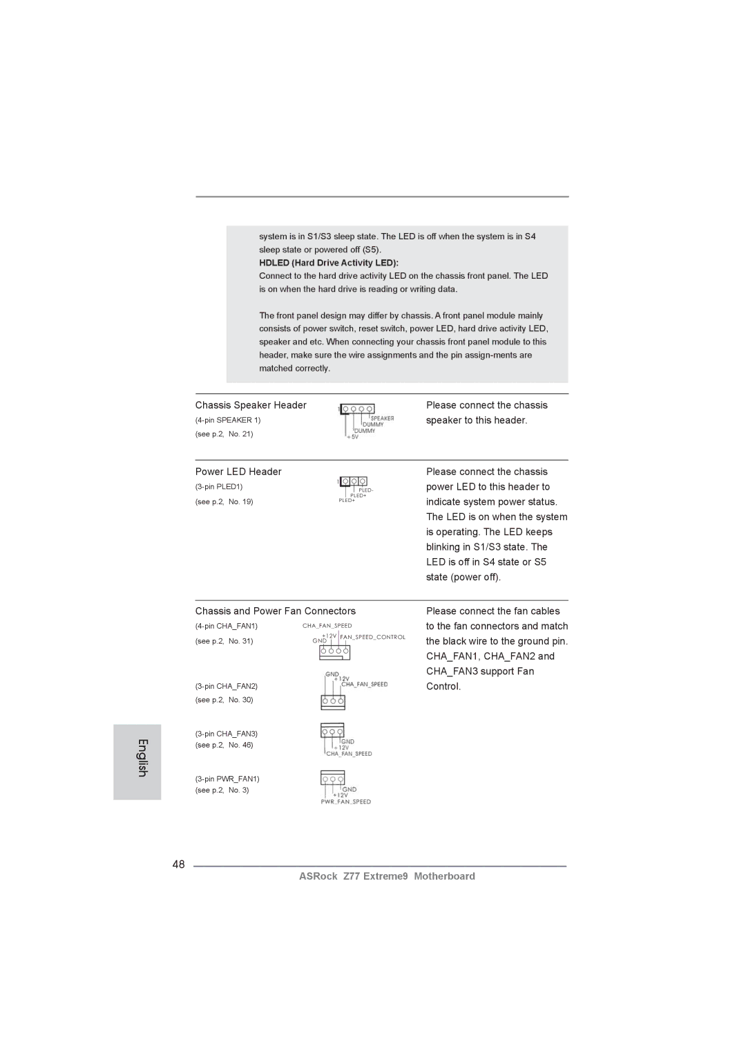
Chassis and Power Fan Connectors
Chassis Speaker Header
Speaker to this header
Hdled Hard Drive Activity LED
Match the black wire to
ATX Power Connector Please connect an ATX power
Supply to this connector
ATX 12V Power Connector
Serial port module
Smart Switches
English 15 Dr. Debug
Status Code Description
English
English
English
English Driver Installation Guide
Installing Windows XP / XP 64-bit Without RAID Functions
\ RAID Installation Guide
Install Windows XP / XP 64-bit OS on your system
English
Click Expert Mode
Teaming Function Operation Guide
English
English
Configure the team IP address
From Control Panel, double-clickNetwork Connections
Bios Information
Kartoninhalt
Deutsch
Spezifikationen Deutsch
Anschlüsse
An der Rückseite
Schnellschalter
CD d’assistance
Einzigartige
Eigenschaft
Hardware Monitor
Zertifizierungen
Warnung
Vorsicht
Deutsch
Systems nach Aufrufen des S4/S5-Zustands automatisch ein
Deutsch
Einstellung der Jumper
Jumper Einstellun Beschreibung
Cmos löschen
Integrierte Header und Anschlüsse
Seriell-ATA2-Anschlüsse
Seriell-ATA3-Anschlüsse
Serial ATA- Sata Datenkabel
Serial ATA- Sata Stromversorgungskabel
USB 3.0-Header
Dieser Header unterstützt ein
Optionales, drahtloses Sende
Und Empfangs-Infrarotmodul
Consumer Infrared-Modul-Header Dieser Header kann zum
Gehäuselautsprecher-Header Schließen Sie den
Diesen Header an
Gehäuse und Strom lüfteranschlüsse
Lüfterkabel mit diesem
ATX-Netz-Header Verbinden Sie die ATX
Header
ATX 12V Anschluss
Schnellschalter
BIOS-Information
Français
Contenu du paquet
Spécifications
VGA sur carte
LAN sans fil
Panneau arrière
USB
Connecteurs
Interrupteur
Rapide
Caractéristique
Unique Voir Attention
Surveillance
Système
Français
Français
Français
Réglage des cavaliers
Le cavalier Description
Effacer la Cmos
En-têtes et Connecteurs sur Carte
Connecteurs Série ATA2
Disque dur Sata / SATA2
SATA3 sur la carte
Sata sur le connecteur
’alimentation sur chaque unité
Connectez ensuite l’extrémité
Blanche du cordon
Cet en-tête supporte un module
Et de réception sans fil
Pour connecter des récepteur
Connecteur audio panneau
En-tête du haut-parleur Veuillez connecter le De châssis
En-tête
LED di accensione
En-tête d’alimentation ATX Veuillez connecter l’unité
Tête
Connecteur ATX
Un module de port COM
Interrupteur rapides
Informations sur le Bios Informations sur le CD de support
Italiano
Contenuto della confezione
100
Specifiche
101
102
Pannello
Posteriore I/O
Connettori SATA3 6,0Gb/s Z77 Intel, supporto RAID
103
Connettori
Interruttore
Interruttore pulizia Cmos con LED
104
105
Avviso
106
107
108
Setup dei Jumpers
Resettare la Cmos
109
Jumper Settaggio del Jumper
Collettori e Connettori su Scheda
110
Connettori Serial ATA2
Cavo d’alimentazione Serial ATA Sata
111
112
Connettore audio sul
Pannello frontale
Collettore pannello di sistema
113
Collettore casse telaio Collegare le casse del telaio a
Questo collettore
Pled LED alimentazione del sistema
114
115
Connettore alimentazione SLI/XFIRE
Utilizzato per supportare il
Modulo porta COM
Interruttori rapidi
116
117
Español
Contenido de la caja
118
Especificación
119
120
LAN inalámbrica
Entrada/Salida de I/O Panel
121
Conectores
Rápido
122
CD de soport
Característica
Única
123
Certificaciones
124
125
126
Setup de Jumpers
Jumper Setting
127
Limpiar Cmos
Cabezales y Conectores en Placas
128
Conexiones de serie ATA2
Cable de alimentación de serie ATA Sata
129
130
Conector de audio de
Panel frontal
Cabezal de panel de sistema
131
Cabezal del altavoz del chasis
Su cabezal
Pled LED de alimentación del sistema
132
Cabezal de alimentación ATX Conecte la fuente de
Cabezal
133
Conector de alimentaciónSLI/XFIRE
Se utiliza para admitir un
Módulo de puerto COM
Conmutadores rápidos
134
Bios Información Información de Software Support CD
135
Введение
136
137
138
139
140
141
Осторожно
142
143
144
145
Перемычка Установка Описание
Колодки и разъемы на плате
146
147
Кабель питания Serial ATA Sata
148
Reset кнопка сброса
149
Pwrbtn кнопка питания
Pled индикатор питания системы
150
Контакты 1-3 подключены
151
Быстрое переключение
152
Информация о Bios
153
Türkçe
154
155
156
Ses
Kablosuz LAN
Arka Panel
157
158
Donanım
Monitör
Sertifikalar
Dİkkat
159
160
161
162
163
Jumper Ayar
CMOS’u temizleme
164
165
166
Ön Panel Ses Fişi
Sistem Paneli Fişi
Işlevini barındırır
167
Kasa Hoparlörü Fişi
Bağlayın
Güç LED’i Fişi
168
169
Ieee 1394 Fişi
Hdmispdif Fişi
170
Bios Bilgileri Yazılım Destek CD’si bilgileri
171
172
ATX 폼 팩터 12.0 x 9.6, 30.5 x 24.4 cm
173
174
175
176
177
178
179
점퍼세팅
180
Cmos 초기화
181
182
183
콘넥터는 오디오 장치를 하게 조절하고 연결할 수 있는 전면 오디오 인터페이스 입니다
시스템 콘넥터
능을 지원하기 위한 것입니다
184
새시 스피커 헤더
십시오
전원 LED 헤더
185
186
Ieee 1394 헤더
지원합니다
Hdmispdif 헤더
187
전원 스위치는 빠른 스위치로서 , 사용자가 시스템을 빠르게 켜거 나 끌 수 있습니다 리셋 스위치
리셋 스위치는 빠른 스위치로서 , 사용자가 시스템을 빠르게 리셋 할 수 있습니다 Cmos 삭제 스위치
Cmos 삭제 스위치는 빠른 스위 치로서 , 사용자가 Cmos 값을 빠르게 삭제할 수 있습니다
시스템 바이오스 정보 소프트웨어 지원 CD 정보
188
189
ATX フォームファクター 12.0-in x 9.6-in, 30.5 cm x 24.4 cm
シリアル l ATA Sata HDD 用電源変換ケーブル(オプション)
190
191
1920x1200 @ 60Hz の最大解像度で Hdmi 1.4a をサポート
PXE をサポート
Ieee 1394 ポート x クリア Cmos スイッヱ(LED 付き)x
192
193
194
195
196
197
ジャンパ設定
198
オンボードのヘッダとコネクタ類。
199
200
USB 3.0 ヘッダ
201
202
203
ATX パワーコネクタ ATX 電源コネクタを接続します。
204
ジュールをサポートします。
205
このマザーボードは Microsoft Windows 7 / 7 64-bit / VistaTM / VistaTM
主板簡介
206
主板規格
207
208
板載 LAN 功能
209
連接頭
210
華擎除濕功能(見警告 18)
警告!
211
212
11、SmartView 是 Internet 瀏覽器的一項新功能,它作為 IE 的智能起始頁
23、EuP, 全稱 Energy Using Product 能耗產品 , 是歐盟用來定義完整系統
213
跳線設置
214
板載接頭和接口
215
216
USB 3.0 擴展接頭
217
開啟前置麥克風。
218
電源指示燈連接排針
219
到這個接頭。
快速開關
220
支持光盤信息
221
電子信息產品污染控制標示
222
主機板簡介
223
224
ATX 規格 12.0 英吋 x 9.6 英吋 , 30.5 公分 x 24.4 公分
225
Intel Z77 的 SATA3 6.0Gb/s 接頭,支援 RAID RAID
USB Intel Z77 的後置 USB 3.0 接頭,支援 USB 1.0/2.0/3.0 5Gb/s
226
227
228
229
230
231
默認設置
232
233
234
系統面板接頭
啟鍵等各種連線。
機箱喇叭接頭請將機箱喇叭連接到這個接頭。
235
236
237
238
本主板支援各種微軟 Windows 操作系統:Microsoft Windows 7/7 64 位元
Isi Paket
239
Spesifikasi
240
241
LAN Nirkabel
Papan Belakang
Ciri-ciri Bios
242
Penghubung
Beralih
243
Fitur Unik
Penjaga
Sertifikasi
Installing OS on a HDD Larger Than 2TB in Ahci Mode
244
245
Bit ..\i386\Win7VistaIntel Bit ..\AMD64\Win7-64Vista64Intel
246
Windows VistaTM 64-bit
247
248
Windows 7 64-bit