Rev. A.5, 8/03 | Page- 4 |
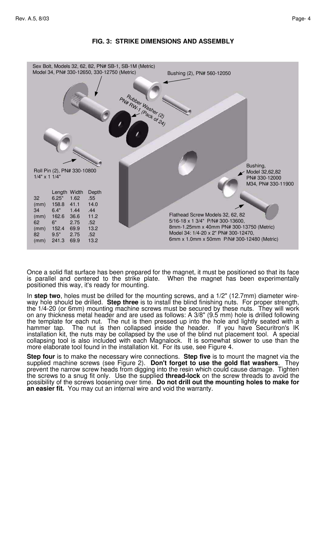
FIG. 3: STRIKE DIMENSIONS AND ASSEMBLY
Sex Bolt, Models 32, 62, 82, PN# |
|
Model 34, PN# | Bushing (2), PN# |
|
| R |
|
|
|
|
|
|
|
|
|
|
|
|
|
| |
P |
|
| u |
|
|
|
|
|
|
|
|
|
|
|
|
|
|
|
| b |
|
|
|
|
|
|
|
|
|
|
|
|
| ||
N |
|
| b |
|
|
|
|
|
|
|
|
|
|
| |||
| # |
|
|
| e |
|
|
|
|
|
|
|
|
|
| ||
|
|
| RW |
| r |
| a |
|
|
|
|
|
| ||||
|
|
|
|
| - |
|
| W | s |
|
|
|
|
| |||
|
|
|
|
|
| 1 | ( |
|
| h |
|
|
|
| |||
|
|
|
|
|
|
|
|
|
|
| e |
|
|
| |||
|
|
|
|
|
|
|
|
| P |
|
|
| r |
|
| ||
|
|
|
|
|
|
|
|
|
| a |
|
|
| ( |
| ||
|
|
|
|
|
|
|
|
|
|
| c |
|
|
| 2 | ||
|
|
|
|
|
|
|
|
|
|
|
| ko |
|
| ) | ||
|
|
|
|
|
|
|
|
|
|
|
|
|
| f |
| ||
|
|
|
|
|
|
|
|
|
|
|
|
|
|
| 2 |
| |
|
|
|
|
|
|
|
|
|
|
|
|
|
|
|
| 4 | |
|
|
|
|
|
|
|
|
|
|
|
|
|
|
|
|
| ) |
Roll Pin (2), PN#
| Length | Width | Depth |
32 | 6.25" | 1.62 | .55 |
(mm)158.8 41.1 14.0
34 | 6.4" | 1.44 | .44 |
(mm)162.6 36.6 11.2
62 6" 2.75 .52
(mm)152.4 69.9 13.2
82 | 9.5" | 2.75 | .52 |
(mm) | 241.3 | 69.9 | 13.2 |
Bushing,
![]() Model 32,62,82
Model 32,62,82
PN#
M34, PN#
Flathead Screw Models 32, 62, 82
6mm x 1.0mm x 50mm P/N#
Once a solid flat surface has been prepared for the magnet, it must be positioned so that its face is parallel and centered to the strike plate. When the magnet has been experimentally positioned this way, it's ready for mounting.
In step two, holes must be drilled for the mounting screws, and a 1/2" (12.7mm) diameter wire- way hole should be drilled. Step three is to install the blind finishing nuts. For proper strength, the
Step four is to make the necessary wire connections. Step five is to mount the magnet via the supplied machine screws (see Figure 2). Don't forget to use the gold flat washers. They prevent the narrow screw heads from digging into the resin which could cause damage. Tighten the screws to a snug fit only. Use the supplied