Rev. A.5, 8/03 | Page- 15 |
wires, while observing correct polarity. The lock, however, automatically detects whether it is receiving 12 or 24 volts and draws the correct amount of current for that voltage (the current is twice as high when the lock is receiving 12 volts than when it is receiving 24 volts). The model 32 series has separate models for 12 and 24 volt operation.
It is good practice to use power supplies with 1/3 extra capacity beyond the current requirements of the load. This greatly reduces the possibility of heat induced power supply failure and also allows for future expansion. Power supply cost is a small fraction of the job cost and should not be skimped on.
Switches may be wired as necessary between the Magnalock and power source. Internal circuitry eliminates inductive kickback, so neither electromechanical switches nor solid state devices will be damaged by arcing when the Magnalock is shut off.
3.3 AVOIDING POOR RELEASE CHARACTERISTICS
One of the exceptional features of Magnalocks is near instantaneous release. This is particularly valuable when the lock is being switched off and the door is being opened at the same time as occurs when a switched exit device like Securitron’s Touch Sense Bar is being used. Two separate wiring errors can however cause Magnalocks to release slowly (in one or two seconds) and this is annoying.
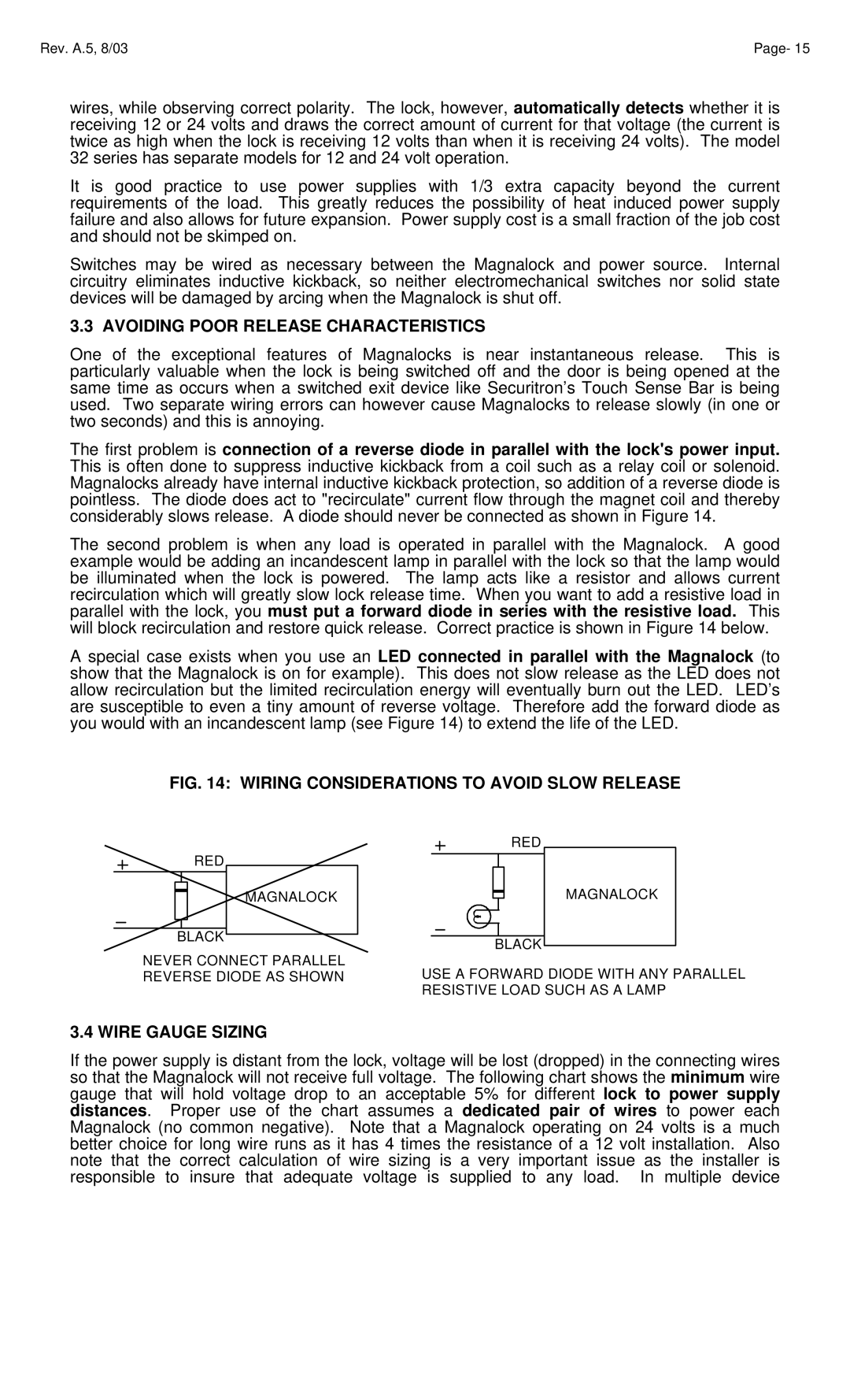
The first problem is connection of a reverse diode in parallel with the lock's power input. This is often done to suppress inductive kickback from a coil such as a relay coil or solenoid. Magnalocks already have internal inductive kickback protection, so addition of a reverse diode is pointless. The diode does act to "recirculate" current flow through the magnet coil and thereby considerably slows release. A diode should never be connected as shown in Figure 14.
The second problem is when any load is operated in parallel with the Magnalock. A good example would be adding an incandescent lamp in parallel with the lock so that the lamp would be illuminated when the lock is powered. The lamp acts like a resistor and allows current recirculation which will greatly slow lock release time. When you want to add a resistive load in parallel with the lock, you must put a forward diode in series with the resistive load. This will block recirculation and restore quick release. Correct practice is shown in Figure 14 below.
A special case exists when you use an LED connected in parallel with the Magnalock (to show that the Magnalock is on for example). This does not slow release as the LED does not allow recirculation but the limited recirculation energy will eventually burn out the LED. LED’s are susceptible to even a tiny amount of reverse voltage. Therefore add the forward diode as you would with an incandescent lamp (see Figure 14) to extend the life of the LED.
FIG. 14: WIRING CONSIDERATIONS TO AVOID SLOW RELEASE
RED
MAGNALOCK
BLACK
NEVER CONNECT PARALLEL REVERSE DIODE AS SHOWN
RED
MAGNALOCK
BLACK
USE A FORWARD DIODE WITH ANY PARALLEL RESISTIVE LOAD SUCH AS A LAMP
3.4 WIRE GAUGE SIZING
If the power supply is distant from the lock, voltage will be lost (dropped) in the connecting wires so that the Magnalock will not receive full voltage. The following chart shows the minimum wire gauge that will hold voltage drop to an acceptable 5% for different lock to power supply distances. Proper use of the chart assumes a dedicated pair of wires to power each Magnalock (no common negative). Note that a Magnalock operating on 24 volts is a much better choice for long wire runs as it has 4 times the resistance of a 12 volt installation. Also note that the correct calculation of wire sizing is a very important issue as the installer is responsible to insure that adequate voltage is supplied to any load. In multiple device