Rev. A.5, 8/03 | Page- 5 |
FIG. 4: COLLAPSING THE BLIND NUTS
DRILL 3/8" (9.5MM) HOLE
PRESS IN BLIND
NUT AS SHOWN
COLLAPSES WHEN CAP SCREW IS TURNED WITH ALLEN WRENCH WHILE TOOL IS HELD FAST WITH BOX WRENCH
BLIND NUT
![]()
![]()
![]()
![]()
![]()
![]()
![]()
![]()
![]()
![]()
![]() HEADER
HEADER
HOLD WITH WRENCH OR |
|
| KNURL |
|
| ||
VISE GRIP WHILE TURNING |
|
| |
|
| TOOL | |
CAP SCREW |
|
| |
|
|
| |
TWO FLAT WASHERS |
|
| CAP |
|
| ||
|
| ||
IF SCREW IS STIFF TO TURN, |
|
| |
|
| ||
ADD LUBRICANT TO WASHERS |
|
| |
|
|
|
WHILE TURNING WITH ALLEN
WRENCH, PRESS IN TO KEEP
NUT SEATED IN HEADER
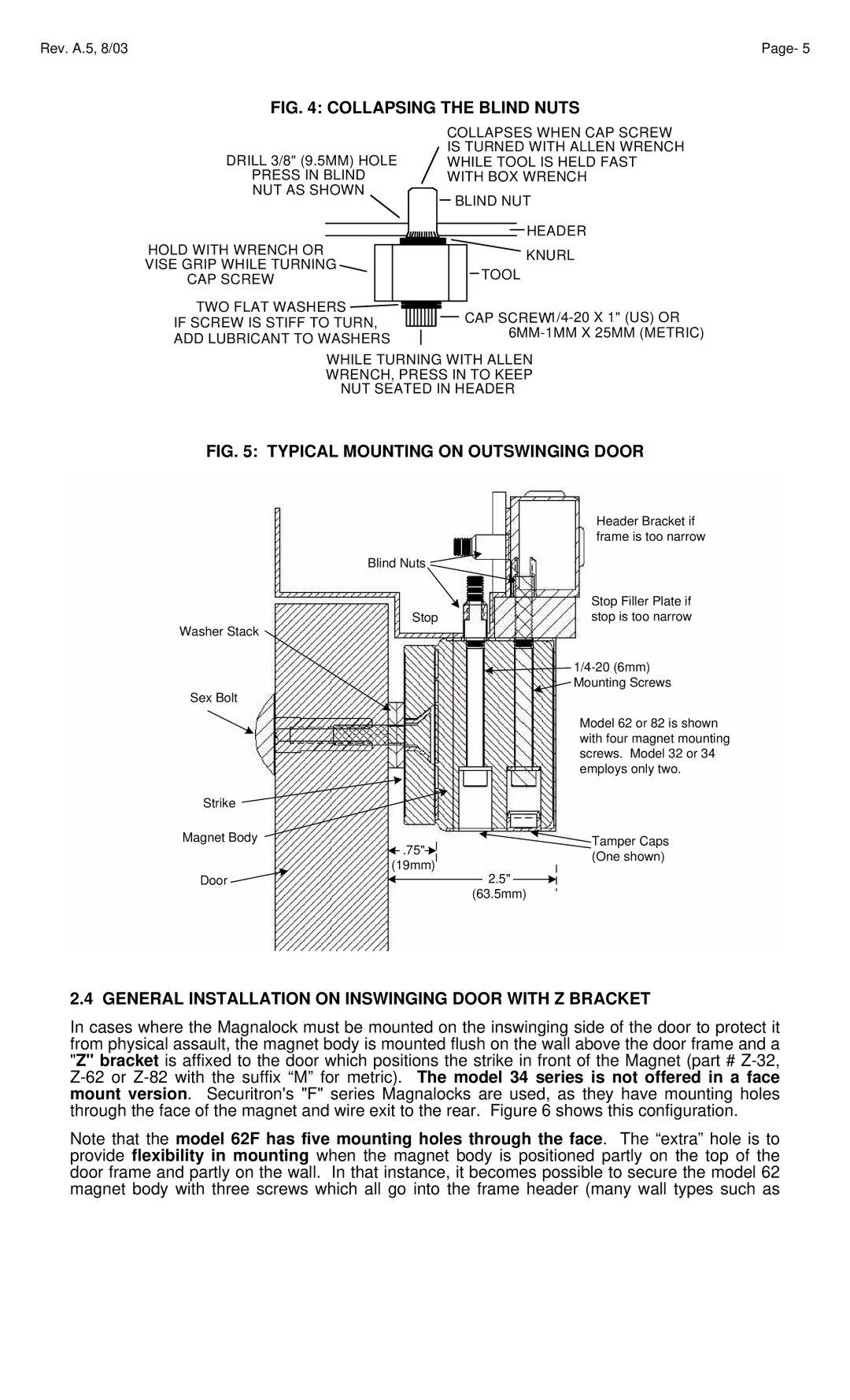
FIG. 5: TYPICAL MOUNTING ON OUTSWINGING DOOR
| Header Bracket if |
| frame is too narrow |
Blind Nuts |
|
| Stop Filler Plate if |
Stop | stop is too narrow |
Washer Stack |
|
| |
Sex Bolt | Mounting Screws |
|
Strike
Magnet Body
![]() .75"
.75"![]()
![]()
(19mm)
Door |
| 2.5" |
|
(63.5mm)
Model 62 or 82 is shown with four magnet mounting screws. Model 32 or 34 employs only two.
Tamper Caps (One shown)
2.4 GENERAL INSTALLATION ON INSWINGING DOOR WITH Z BRACKET
In cases where the Magnalock must be mounted on the inswinging side of the door to protect it from physical assault, the magnet body is mounted flush on the wall above the door frame and a "Z" bracket is affixed to the door which positions the strike in front of the Magnet (part #
Note that the model 62F has five mounting holes through the face. The “extra” hole is to provide flexibility in mounting when the magnet body is positioned partly on the top of the door frame and partly on the wall. In that instance, it becomes possible to secure the model 62 magnet body with three screws which all go into the frame header (many wall types such as