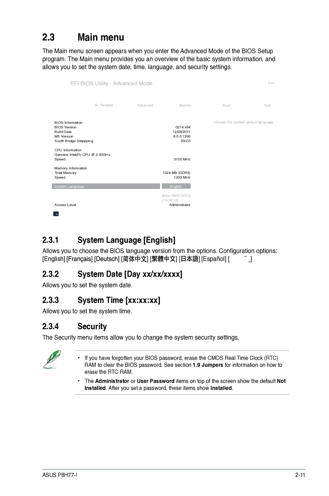
Motherboard
 Offer to Provide Source Code of Certain Software
Copyright 2013 ASUSTeK Computer Inc. All Rights Reserved
 Contents
 CPU Configuration PCH Configuration
Asus Bios Updater
System Language English
Network Stack
 Anti Surge Support Enabled
 Operation safety
Safety information
Electrical safety
 How this guide is organized
Where to find more information
About this guide
 Bold text
Conventions used in this guide
Typography
 PCI Express 3.0/2.0 x16 slot
P8H77-I specifications summary
 Bios
 Welcome
Package contents
Special features
 Native Sata 6.0 Gb/s support
Intel H77 Express Chipset
Complete USB 3.0 Integration
PCIe 3.0 Ready
 Innovative Asus features
 GPU Boost
USB 3.0 Boost
Asus Q-Fan
Asus Fan Xpert
 ErP ready
LucidLogix Virtu MVP
R. CPU Parameter Recall
 Before you proceed
Standby Power LED
Standby Power Powered Off
 Screw holes
Placement direction
Motherboard overview
 Motherboard layout
Layout contents
 To install a CPU Locate the CPU socket on the motherboard
Installing the CPU
Central Processing Unit CPU
Load lever Retention tab
 CPU notches Gold triangle mark Alignment keys
Load plate
 Retention tab
Insert the load lever under
 Installing the CPU heatsink and fan
 Uninstalling the CPU heatsink and fan
P8H77-I CPU fan connector
 P8H77-I 240-pin DDR3 Dimm sockets
System memory
Overview
 DDR3-2250 MHz capability
Memory configurations
 DDR3-2133 MHz capability
DDR3-2200 MHz capability
DDR3-2000 MHz capability
DDR3-1866 MHz capability
 DDR3-1600 MHz capability
 DDR3-1333 MHz capability
 Vendors Size Chip Brand Chip no Timing Voltage Dimm socket
 SS Single-sided / DS Double-sided Dimm support
DDR3-1066 MHz capability
 Remove the Dimm from the socket
Installing a Dimm
Removing a Dimm
 Configuring an expansion card
Installing an expansion card
Expansion slots
PCI Express x16 slots
 Clear RTC RAM 3-pin Clrtc
Jumpers
 Rear panel connectors
Connectors
Audio 2, 4, 6, or 8-channel configuration
LAN port LED indications
 Asus P8H77-I
 P8H77-I Digital audio connector
Internal connectors
Front panel audio connector 10-1 pin Aafp
P8H77-I Front panel audio connector
 CPU, and chassis fan connectors 4-pin CPUFAN, 4-pin Chafan
P8H77-I ATX power connectors
ATX power connectors 24-pin EATXPWR, 4-pin ATX12V
 P8H77-I System panel connector
P8H77-ISpeaker Out Connector
 See .5.3 Sata Configuration for details
P8H77-I Sata 3.0Gb/s connectors
 USB 3.0 connector 20-1 pin USB334
P8H77-I USB3.0 Front panel connector
 USB connectors 10-1 pin USB78
P8H77-I USB2.0 connector
 Click an item to install
Installing an operating system
Software support
Support DVD information
 Asus Update utility
Managing and updating your Bios
Installing Asus Update
Updating the Bios
 Asus EZ Flash
To update the Bios using EZ Flash
Select Update Bios from file, then click Next
 To recover the Bios
Asus CrashFree Bios 3 utility
Recovering the Bios
 Booting the system in DOS environment
Asus Bios Updater
Before updating Bios
 Filename Extension
Backing up the current Bios
To backup the current Bios file using the Bios Updater
 To update the Bios file using Bios Updater
Updating the Bios file
 Entering Bios Setup after Post
Bios setup program
Entering Bios Setup at startup
 EZ Mode
Bios menu screen
 Menu items
Advanced Mode
Back button
Submenu items
 Pop-up window
Configuration fields
Scroll bar
Navigation keys
 System Language English
Main menu
System Date Day xx/xx/xxxx
System Time
 User Password
Administrator Password
 Ai Tweaker menu
 Memory Frequency Auto
CPU Power Management
IGPU Max. Frequency
GPU Boost OK
 Dram Voltage Auto
CPU Voltage Auto
IGPU Offset Voltage Auto
 PCH Voltage Auto
Advanced menu
Vccsa Voltage Auto
 CPU Configuration
 Sata Configuration
PCH Configuration
 System Agent Configuration
 Onboard Devices Configuration
USB Configuration
 Network Stack
7 APM
 12V Voltage
Monitor menu
 CPU Q-Fan Control Enabled
CPU Temperature / MB Temperature xxxºC/xxxºF
CPU / Chassis Fan Speed xxxx RPM or Ignore / N/A
CPU Fan Speed Low Limit 200 RPM
 Anti Surge Support Enabled
Chassis Q-Fan Control Enabled
On the chassis temperature
CPU Voltage, 3.3V Voltage, 5V Voltage, 12V Voltage
 Bootup NumLock State On
Boot menu
Full Screen Logo Enabled
Wait for ‘F1’ If Error Enabled
 Setup Mode EZ Mode
Option ROM Messages Force Bios
UEFI/Legacy Boot Enabled both Uefi and Legacy
Boot Option Priorities
 Asus EZ Flash 2 Utility
Tools menu
Asus O.C. Profile
Asus SPD Information
 Exit menu
 IC Canadian Compliance Statement
Federal Communications Commission Statement
 Canadian Department of Communications Statement
Asus Recycling/Takeback Services
 Telephone
Address
Online support
Support fax
 EC Declaration of Conformity
Declaration of Conformity