Motherboard
E3465 First Edition February
Contents
Chapter Bios setup
Chapter Powering up
Switches Audio card installation Connectors
Psmi Ipmi FRU
Appendix CPU features
Chapter Software support
Federal Communications Commission Statement
Canadian Department of Communications Statement
Electrical safety
Safety information
Operation safety
About this guide
Where to find more information
How this guide is organized
Typography
Conventions used in this guide
Italics
Z7S WS specifications summary
USB
Asus EZ DIY
Xiii
Xiv
Features and the new technologies it supports
Chapter
Chapter summary
Package contents
Welcome
Special features
Product highlights
Ieee 1394a support
Dual Gigabit LAN solution
Serial ATA 3.0 Gb/s technology and SATA-On-The-Go
Diagnosis card
CrashFree Bios
Innovative Asus features
Temperature, fan, and voltage monitoring
Asus MemCool FB-DIMM Fan Kit optional
Hardware
Chapter summary
Before you proceed
Onboard LED
Motherboard overview
Placement direction
Screw holes
Support kits for the motherboard
CEK spring screw hole
That should match the eight 8 CEK spring screw holes
Motherboard layout
Audio card layout
Layout contents
CPU0FAN, CPU1FAN, CHAFAN1-4
To install a CPU Locate the CPU socket on the motherboard
Installing the CPU
Central Processing Unit CPU
CPU notch
Asus Z7S WS
To install the CPU heatsink and fan
Installing the CPU heatsink and fan
CPU heatsink top view
Z7S WS CPU fan connectors
System memory
Memory configurations
Overview
Dimm installation reference table
Rank population
Memory sparing technology
Memory Sparing
To remove a Dimm
Installing a Dimm
Removing a Dimm
Remove the Dimm from the socket
Installing the MemCool FB-DIMM fan optional
Asus Z7S WS
To install an expansion card
Installing an expansion card
Configuring an expansion card
Expansion slots
PCI Express 2.0 x16 slots red
Interrupt assignments
PCI Express x1 MIO slot
Universal PCI Express x16 slot white
7 PCI/PCI-X slots
Jumpers
Clear RTC RAM Clrtc
PCI-X Speed setting 3-pin PCIXSPEED1
Jumper cap on pins 2-3100 MHz capability for the PCI-X slot
Switches
Fan switches HMSW1
Audio card installation
Take out the Audio card from the package
Connectors
Rear panel connectors
Audio 2, 4, 6, or 8-channel configuration
LAN port LED indications
Internal connectors
Floppy disk drive connector 34-1 pin FLOPPY1
IDE connector 40-1 pin Priide
Cable connector
Serial ATA connectors 7-pin SATA1-6
Serial ATA hard disk drive connection
USB connectors 4-pin USB6, 10-1 pin USB78
Z7S WS USB connectors
Serial port connector 10-1 pin COM1
Power supply SMBus connector 5-pin PSUSMB1
Chassis intrusion connector 4-1 pin Chassis
Eatxpwr EATX12V
TPM connector 20-1 pin TPM Optional
ATX power button/soft-off button Green 2-pin Pwrsw
System panel connector 20-pin Panel
System power LED Green 3-pin Pled
Reset button Blue 2-pin Reset
Front panel audio connector 10-1 pin Aafp
Optical drive audio connector 4-pin CD
Connector system panel
Installing G.P. Diagnosis card
10 G.P. Diagnosis card installation
10.1 G.P. Diagnosis card layout
10.3 G.P. Diagnosis card check codes
Hardware information
Sequence, and ways of shutting down
System
Starting up for the first time Turning off the computer
AMI Bios beep codes
Starting up for the first time
Using the dual function power switch
Using the OS shut down function
Turning off the computer
Bios setup
Chapter summary
Asus Update utility
Managing and updating your Bios
Installing Asus Update
Updating the Bios through the Internet
Updating the Bios through a Bios file
Windows XP environment
Creating a bootable floppy disk
DOS environment
Windows Vista environment
Asus EZ Flash 2 utility
Z7S WS
To copy the current Bios file using the Afudos utility
Copying the current Bios
Updating the Bios file
To update the Bios file using the Afudos utility
Utility verifies the file and starts updating the Bios
Recovering the Bios from the support DVD
Asus CrashFree Bios 3 utility
Recovering the Bios from the USB flash disk
Bios setup program
Updating your Bios
Menu bar
Bios menu screen
Navigation keys
Sub-menu items
Configuration fields
Menu items
Pop-up window
System Time
Main menu
System Date Day xx/xx/xxxx
Legacy Diskette a 1.44M, 3.5
Type Auto
LBA/Large Mode Auto
Primary / Secondary / Third IDE Master / Slave
Block Multi-sector Transfer Auto
Storage Configuration
Ahci Port1~6
Ahci Configuration
Configure Sata as IDE
Displays the status of auto-detection of Sata devices
System Memory
System Information
Processor Information
+1.8v Dual Adjustment +1.80v
Jumpless Configuration
Fixed +1.25v Adjustment +1.25v
SB +1.5v Adjustment +1.50v
Ratio Cmos Setting
CPU Configuration
Marvell Post Check LAN cable Disabled
Ai Net
Adjacent Cache Line Prefectch Enabled
C1E Support Enabled
Hardware Prefetcher Enabled
Max Cpuid Value Limit Disabled
Clock Mode Select Auto
Onboard Devices Configuration
This menu allows you to select the Clock Generator mode
Clock Generator
Onboard LAN Enabled
Micro eSATA/PATA Controller Enabled
Onboard 1394 Enabled
Serial Port1 Address 3F8/IRQ4
PCIPnP
USB Configuration
Trusted Computing
TCG/TPM Support No
Acpi 2.0 Support Disabled
Power menu
Suspend Mode Auto
Acpi Apic Support Enabled
APM Configuration
Configuration options Disabled Space Bar Power Key Ctrl-Esc
Power On By RTC Alarm Disabled
Power On By PS/2 Keyboard Disabled
Hardware Monitor
MB Target Temperature
Smart Fan Control Enabled
CPU0/1 Target Temperature
CPU0/1 Fan Speed xxxxRPM or Ignored / N/A
Boot Device Priority
Boot menu
1st ~ xxth Boot Device xxx Drive
Boot Settings Configuration
Change Supervisor Password
Security
Clear User Password
User Access Level Full Access
Change User Password
Password Check Setup
Tools menu
Asus EZ Flash
Load from Profile 1/2
Asus O.C. Profile
Save to Profle 1/2
Start O.C. Profile
Exit & Save Changes
Load Setup Defaults
Exit menu
Exit & Discard Changes
Bios setup
Support
Installing an operating system
Support DVD information
Installing an operating system
Running the support DVD
Drivers menu
Utilities menu
Asus InstAll Installation Wizard for Utilities
Installs the Marvell Yukon CPA Application
Marvell Yukon VCT Application
Asus PC Probe
Asus Update
CyberLink PowerBackup
Asus AI Nap
IntelR ESB2 AHCI/RAID 32bit/64bit Driver
Make Disk menu
JMicron JMB36X 32bit/64bit SATA/RAID Driver
Manual menu Asus Contact information
Other information
Displays the general specifications of the motherboard
Displays the support DVD contents in graphical format
Motherboard Info
Technical support Form
Filelist
Software information
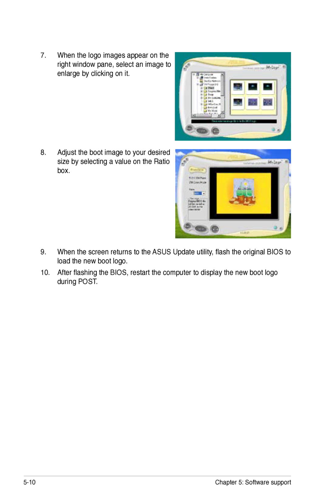
Asus MyLogo2
Software support
Using the Virtual Cable Tester
AI NET2
Asus PC Probe
Installing PC Probe
Using PC Probe
Launching PC Probe
Preference
Sensor alert
Changing the monitor panels position
Hardware monitor panels
Moving the monitor panels
DMI browser
WMI browser
Monitoring sensor alert
Usage
PCI browser
CPU usage
Configuring PC Probe
Memory usage
Asus AI Nap
Audio configurations
Realtek HD Audio Manager
Minimize
Configuration options
Information
Exit
Audio I/O
Click to effect the Mixer settings and exit
Mixer
To set the Audio I/O options
Click the Noise Suppression
Microphone
3D Audio Demo
RAID configurations
RAID definitions
Intel RAID configurations
Installing Serial ATA hard disks
Setting the RAID item in Bios
Intel Matrix Storage Manager Option ROM Utility
Creating a RAID 0 set striped
Create Array Menu
Are you sure you want to create this volume? Y/N
Creating a RAID 1 set mirrored
XX.X GB
Creating a RAID 5 set parity
Software support
Deleting a RAID set
XXX.XGB
Resetting Disks to Non-RAID
Reset RAID Data
Onboard Device Configuration for details
JMicron RAID Configuration
Before creating a RAID set
Entering the JMB363 RAID Bios utility
Creating a RAID set
Selected HDD shows a sign before it
Disks Select Disk Block N/A Size 159 GB
RDD0 Jraid
RAID
Pressing Y deletes all the data in the HDD
Solving a Mirror conflict
RDD0 Jraid
Saving the settings and exiting setup
Rebuilding a Mirror Drive
Creating a RAID driver disk without entering the OS
Creating a RAID driver disk
Creating a RAID/SATA driver disk in Windows
Software support
Appendix
Intel EM64T Enhanced Intel SpeedStep Technology Eist
Enhanced Intel SpeedStep Technology Eist
Using the Intel EM64T feature
Intel EM64T
System requirements
Using the Eist