•Insulated Rail Joiners: HO - Item #55; N scale - Item #2538
•Mini flathead screwdriver
GETTING STARTED
Decoder Preparation
Before you can use your Commander, you must have a decoder installed in any locomotive you wish to run in DCC mode. Please note that Atlas Dual- Mode Decoders
Setting Up Your Layout to Run DCC
Any analog layout that is run using a standard DC power pack can be con- verted to run as a digital layout controlled by a DCC system. Here are the steps to convert your layout to run DCC using the Atlas Commander:
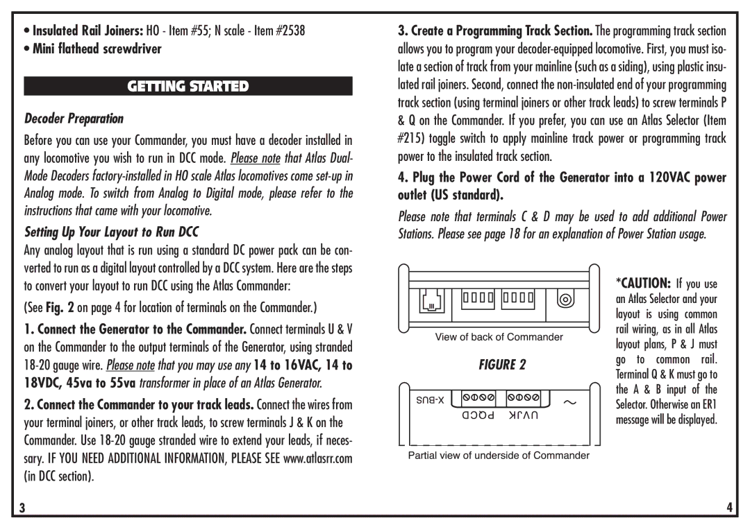
(See Fig. 2 on page 4 for location of terminals on the Commander.)
1.Connect the Generator to the Commander. Connect terminals U & V on the Commander to the output terminals of the Generator, using stranded
2.Connect the Commander to your track leads. Connect the wires from your terminal joiners, or other track leads, to screw terminals J & K on the Commander. Use
3.Create a Programming Track Section. The programming track section allows you to program your
4.Plug the Power Cord of the Generator into a 120VAC power outlet (US standard).
Please note that terminals C & D may be used to add additional Power Stations. Please see page 18 for an explanation of Power Station usage.
|
|
|
|
|
|
|
|
|
|
|
|
|
|
|
| *CAUTION: If you use | |
|
|
|
|
|
|
|
|
|
|
|
|
|
|
|
| ||
|
|
|
|
|
|
|
|
|
|
|
|
|
|
|
| an Atlas Selector and your | |
|
|
|
|
|
|
|
|
|
|
|
|
|
|
|
| ||
|
|
|
|
|
|
|
|
|
|
|
|
|
|
|
| layout is | using common |
|
|
|
|
|
|
|
|
|
|
|
|
|
|
|
| ||
|
|
|
|
|
|
|
|
|
|
|
|
|
|
|
| ||
|
|
|
|
|
|
|
|
|
|
|
|
|
|
|
| rail wiring, as in all Atlas | |
|
|
|
|
|
|
|
|
|
|
|
|
|
|
|
| ||
|
|
|
|
|
|
|
|
|
|
|
|
|
|
|
| layout plans, P & J must | |
|
|
|
|
|
|
|
|
|
|
| FIGURE 2 | go to | common rail. | ||||
|
|
|
|
|
|
|
|
|
|
| Terminal Q & K must go to | ||||||
|
|
|
|
|
|
|
|
|
|
|
|
|
|
|
| ||
|
|
|
|
|
|
|
|
|
|
|
|
|
|
|
| the A & B input of the | |
|
|
|
|
|
|
|
|
|
|
|
|
|
|
|
| ||
|
|
|
|
|
|
|
|
|
|
|
|
|
|
|
| Selector. Otherwise an ER1 | |
|
|
|
|
|
|
|
|
|
|
|
|
|
|
|
| message will be displayed. | |
|
|
|
|
|
|
|
|
|
|
|
|
|
|
|
|
|
|
3 | 4 |