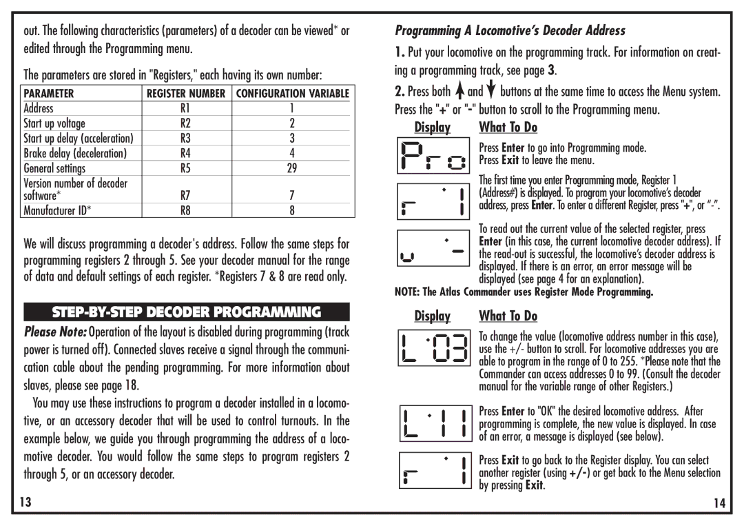
out. The following characteristics (parameters) of a decoder can be viewed* or edited through the Programming menu.
The parameters are stored in "Registers," each having its own number:
| PARAMETER | REGISTER NUMBER | CONFIGURATION VARIABLE |
|
| Address | R1 | 1 |
|
| Start up voltage | R2 | 2 |
|
| Start up delay (acceleration) | R3 | 3 |
|
| Brake delay (deceleration) | R4 | 4 |
|
| General settings | R5 | 29 |
|
| Version number of decoder |
|
|
|
| software* | R7 | 7 |
|
| Manufacturer ID* | R8 | 8 |
|
We will discuss programming a decoder's address. Follow the same steps for programming registers 2 through 5. See your decoder manual for the range of data and default settings of each register. *Registers 7 & 8 are read only.
STEP-BY-STEP DECODER PROGRAMMING
Please Note: Operation of the layout is disabled during programming (track power is turned off). Connected slaves receive a signal through the communi- cation cable about the pending programming. For more information about slaves, please see page 18.
You may use these instructions to program a decoder installed in a locomo- tive, or an accessory decoder that will be used to control turnouts. In the example below, we guide you through programming the address of a loco- motive decoder. You would follow the same steps to program registers 2 through 5, or an accessory decoder.
13
Programming A Locomotive’s Decoder Address
1.Put your locomotive on the programming track. For information on creat- ing a programming track, see page 3.
2.Press both ![]() and
and![]() buttons at the same time to access the Menu system. Press the "+" or
buttons at the same time to access the Menu system. Press the "+" or
Display | What To Do |
| Press Enter to go into Programming mode. |
| Press Exit to leave the menu. |
| The first time you enter Programming mode, Register 1 |
| |
| (Address#) is displayed. To program your locomotive’s decoder |
| address, press Enter. To enter a different Register, press "+", or |
|
|
To read out the current value of the selected register, press Enter (in this case, the current locomotive decoder address). If the
NOTE: The Atlas Commander uses Register Mode Programming.
|
| Display |
|
| What To Do | ||
|
|
| . |
|
|
| To change the value (locomotive address number in this case), |
|
|
|
| ||||
|
| L 03 |
|
|
| use the +/- button to scroll. For locomotive addresses you are | |
|
|
|
|
| able to program in the range of 0 to 255. *Please note that the | ||
|
|
|
|
|
|
| Commander can access addresses 0 to 99. (Consult the decoder |
|
|
| . |
|
|
| manual for the variable range of other Registers.) |
|
| L |
|
|
| Press Enter to "OK" the desired locomotive address. After | |
|
|
|
|
| |||
|
|
|
|
|
| programming is complete, the new value is displayed. In case | |
|
|
|
|
|
| of an error, a message is displayed (see below). | |
|
|
|
|
|
|
| Press Exit to go back to the Register display. You can select |
|
|
|
|
|
| ||
|
|
|
|
|
|
| another register (using |
|
|
|
|
|
|
| by pressing Exit. |
|
|
|
|
|
| ||
|
|
|
|
| 14 | ||
