S3 ELECTRONIC BILGE SWITCH
4801 / 4802
SAVE THESE INSTRUCTIONS
INSTALLATION INSTRUCTIONS | 09/01 | 69460 Rev. B |
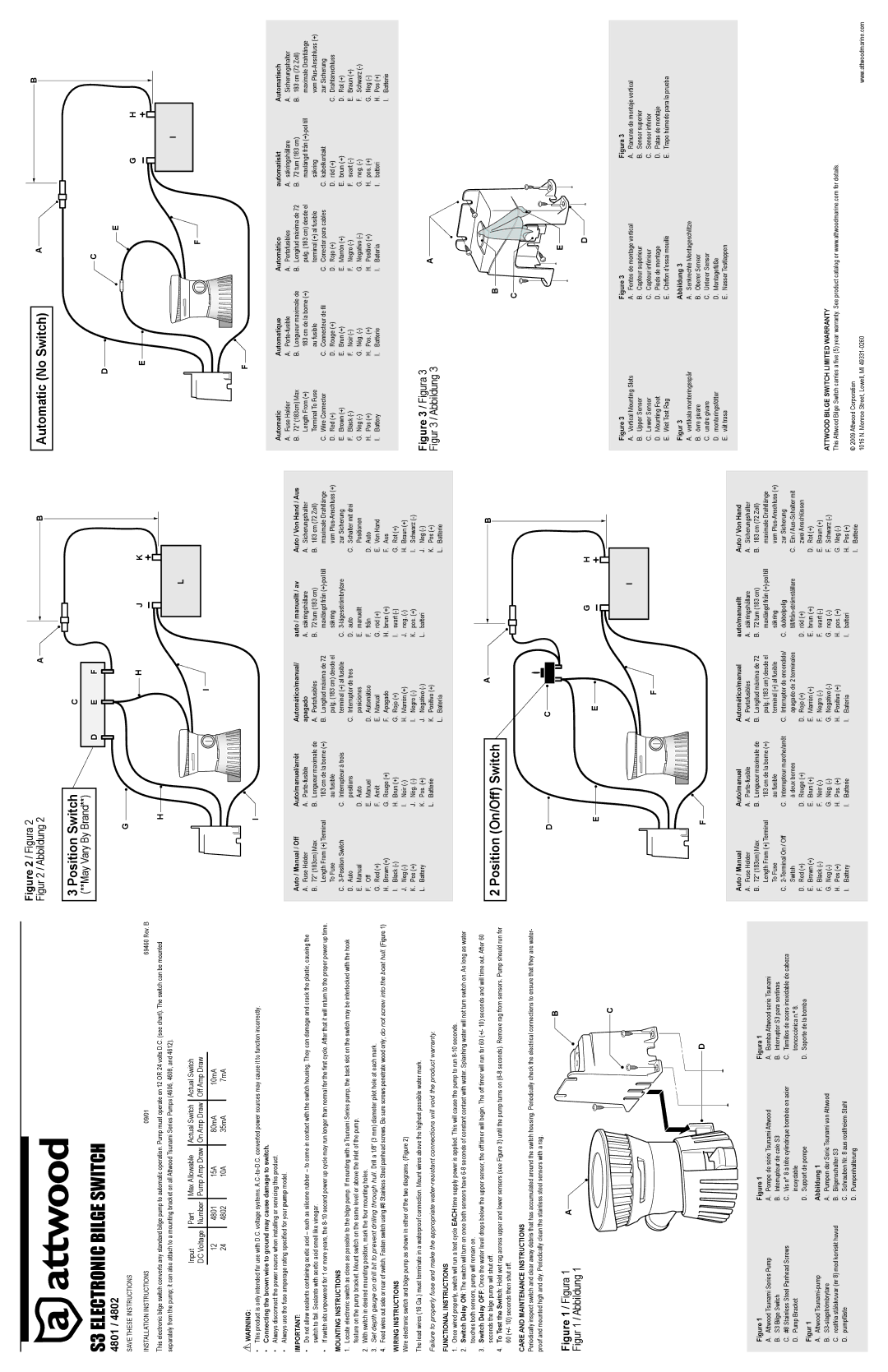
Figure 2 / Figura 2 Figur 2 / Abbildung 2
3 Position Switch
(**May Vary By Brand**)
G
A ![]()
C
D E F
H
B
J K
Automatic (No Switch)
D
E
A
C
E
B
G H
This electronic bilge switch converts any standard bilge pump to automatic operation. Pump must operate on 12 OR 24 volts D.C. (see chart). The switch can be mounted separately from the pump; it can also attach to a mounting bracket on all Attwood Tsunami Series Pumps (4606, 4608, and 4612).
Input |
| Part |
| Max Allowable |
| Actual Switch |
| Actual Switch |
|
|
|
| |||||
DC Voltage |
| Number |
| Pump Amp Draw |
| On Amp Draw |
| Off Amp Draw |
|
|
|
|
|
|
|
|
|
12 |
| 4801 |
| 15A |
| 80mA |
| 10mA |
24 |
| 4802 |
| 10A |
| 35mA |
| 7mA |
!WARNING:
•This product is only intended for use with D.C. voltage systems.
•Connecting the brown wire to ground may cause damage to switch.
•Always disconnect the power source when installing or servicing this product.
•Always use the fuse amperage rating specified for your pump model.
IMPORTANT:
•Do not allow sealants containing acetic acid – such as silicone rubber – to come in contact with the switch housing. They can damage and crack the plastic, causing the switch to fail. Sealants with acetic acid smell like vinegar.
•If switch sits unpowered for 1 or more years, the
MOUNTING INSTRUCTIONS
1.Locate electronic switch as close as possible to the bilge pump. If mounting with a Tsunami Series pump, the back slot on the switch may be interlocked with the hook feature on the pump bracket. Mount switch on the same level or above the inlet of the pump.
2.With switch in desired mounting position, mark the four mounting holes.
3.Set depth gauge on drill bit to prevent drilling through hull. Drill a 1/8” (3 mm) diameter pilot hole at each mark.
4.Feed wires out side or rear of switch. Fasten switch using #8 Stainless Steel panhead screws. Be sure screws penetrate wood only; do not screw into the boat hull. (Figure 1)
WIRING INSTRUCTIONS
Wire electronic switch and bilge pump as shown in either of the two diagrams. (Figure 2)
The lead wires (16 Ga.) must terminate in a waterproof connection. Mount wires above the highest possible water mark.
Failure to properly fuse and make the appropriate
FUNCTIONAL INSTRUCTIONS
H
L |
I
I ![]()
Auto / Manual / Off | Auto/manuel/arrêt | Automático/manual/ | auto / manuellt / av | Auto / Von Hand / Aus | |||||
A. Fuse Holder | A. | apagado | A. säkringshållare | A. Sicherungshalter | |||||
B. | 72″ (183cm) Max | B. Longueur maximale de | A. Portafusibles | B. | 72 tum (183 cm) | B. | 183 cm (72 Zoll) | ||
| Length From (+) Terminal |
| 183 cm de la borne (+) | B. Longitud máxima de 72 |
| maxlängd från |
| maximale Drahtlänge | |
| To Fuse |
| au fusible |
| pulg. (183 cm) desde el |
| säkring |
| vom |
C. | C. Interrupteur à trois |
| terminal (+) al fusible | C. |
| zur Sicherung | |||
D. | Auto |
| positions | C. Interruptor de tres | D. | auto | C. Schalter mit drei | ||
E. | Manual | D. Auto |
| posiciones | E. | manuellt |
| Positionen | |
F. | Off | E. Manuel | D. Automático | F. | från | D. Auto | |||
G. | Red (+) | F. | Arrêt | E. Manual | G. | röd (+) | E. Von Hand | ||
H. | Brown (+) | G. | Rouge (+) | F. | Apagado | H. | brun (+) | F. | Aus |
I. | Black | H. | Brun (+) | G. | Rojo (+) | I. | svart | G. | Rot (+) |
J. | Neg | I. | Noir | H. | Marrón (+) | J. | neg. | H. | Braun (+) |
K. | Pos (+) | J. | Nég. | I. | Negro | K. | pos. (+) | I. | Schwarz |
L. | Battery | K. | Pos. (+) | J. | Negativo | L. | batteri | J. | Neg |
|
| L. | Batterie | K. | Positivo (+) |
|
| K. | Pos (+) |
|
|
|
| L. | Batería |
|
| L. | Batterie |
F
F ![]()
Automatic | Automatique | Automático | automatiskt | Automatisch | |||||
A. Fuse Holder | A. | A. Portafusibles | A. säkringshållare | A. Sicherungshalter | |||||
B. | 72″ (183cm) Max | B. Longueur maximale de | B. Longitud máxima de 72 | B. | 72 tum (183 cm) | B. | 183 cm (72 Zoll) | ||
| Length From (+) |
| 183 cm de la borne (+) |
| pulg. (183 cm) desde el |
| maxlängd från |
| maximale Drahtlänge |
| Terminal To Fuse |
| au fusible |
| terminal (+) al fusible |
| säkring |
| vom |
C. Wire Connector | C. Connecteur de fil | C. Conector para cables | C. kabelkontakt |
| zur Sicherung | ||||
D. Red (+) | D. Rouge (+) | D. Rojo (+) | D. röd (+) | C. Drahtanschluss | |||||
E. Brown (+) | E. Brun (+) | E. Marrón (+) | E. brun (+) | D. Rot (+) | |||||
F. | Black | F. | Noir | F. | Negro | F. | svart | E. | Braun (+) |
G. | Neg | G. | Nég. | G. | Negativo | G. | neg. | F. | Schwarz |
H. | Pos (+) | H. | Pos. (+) | H. | Positivo (+) | H. | pos. (+) | G. | Neg |
I. | Battery | I. | Batterie | I. | Batería | I. | batteri | H. | Pos (+) |
|
|
|
|
|
|
|
| I. | Batterie |
|
|
|
|
|
|
|
|
|
|
Figure 3 / Figura 3 | A | |
Figur 3 / Abbildung 3 | ||
|
1.Once wired properly, switch will run a test cycle EACH time supply power is applied. This will cause the pump to run
2.Switch Delay ON: The switch will turn on once both sensors have
3.Switch Delay OFF: Once the water level drops below the upper sensor, the off timer will begin. The off timer will run for 60 (+/- 10) seconds and will time out. After 60 seconds the bilge pump will shut off.
4.To Test the Switch: Hold wet rag across upper and lower sensors (see Figure 3) until the pump turns on
CARE AND MAINTENANCE INSTRUCTIONS
Periodically inspect switch and clear away debris that has accumulated around the switch housing. Periodically check the electrical connections to ensure that they are water- proof and mounted high and dry. Periodically clean the stainless steel sensors with a rag.
B
Figure 1 / Figura 1 | A |
Figur 1 / Abbildung 1 |
|
C
2 Position (On/Off) Switch
D
E
A
C
E![]()
F
B
G H
I |
| B |
|
| C |
|
| E |
|
| D |
|
Figure 3 | Figure 3 | Figura 3 |
A. Vertical Mounting Slots | A. Fentes de montage vertical | A. Ranuras de montaje vertical |
B. Upper Sensor | B. Capteur supérieur | B. Sensor superior |
C. Lower Sensor | C. Capteur inférieur | C. Sensor inferior |
D. Mounting Feet | D. Pieds de montage | D. Patas de montaje |
E. Wet Test Rag | E. Chiffon d'essai mouillé | E. Trapo húmedo para la prueba |
Figur 3 | Abbildung 3 |
|
A. vertikala monteringsspår | A. Senkrechte Montageschlitze |
|
|
|
|
|
| D |
|
|
|
|
| |
|
|
|
|
| |
|
|
|
|
|
|
|
|
| |||
Figure 1 | Figure 1 | Figura 1 | |||
A. Attwood Tsunami Series Pump | A. Pompe de série Tsunami Attwood | A. Bomba Attwood serie Tsunami | |||
B. S3 Bilge Switch | B. Interrupteur de cale S3 | B. Interruptor S3 para sentinas | |||
C. #8 Stainless Steel Panhead Screws | C. Vis n° 8 à tête cylindrique bombée en acier | C. Tornillos de acero inoxidable de cabeza | |||
D. Pump Bracket | inoxydable |
| troncocónica n.º 8. | ||
Figur 1 | D. Support de pompe | D. Soporte de la bomba | |||
Abbildung 1 |
|
| |||
A. Attwood |
|
| |||
B. | A. Pumpen der Serie Tsunami von Attwood |
|
| ||
C. rostfria stålskruvar (nr 8) med koniskt huvud | B. Bilgenschalter S3 |
|
| ||
D. pumpfäste | C. Schrauben Nr. 8 aus rostfreiem Stahl |
|
| ||
| D. Pumpenhalterung |
|
| ||
|
|
|
|
|
|
F![]()
Auto / Manual | Auto/manuel | Automático/manual | auto/manuellt | Auto / Von Hand | |||||
A. Fuse Holder | A. | A. Portafusibles | A. säkringshållare | A. Sicherungshalter | |||||
B. | 72″ (183cm) Max | B. Longueur maximale de | B. Longitud máxima de 72 | B. | 72 tum (183 cm) | B. | 183 cm (72 Zoll) | ||
| Length From (+) Terminal |
| 183 cm de la borne (+) |
| pulg. (183 cm) desde el |
| maxlängd från |
| maximale Drahtlänge |
| To Fuse |
| au fusible |
| terminal (+) al fusible |
| säkring |
| vom |
C. | C. Interrupteur marche/arrêt | C. Interruptor de encendido/ | C. dubbelpolig |
| zur Sicherung | ||||
| Switch |
| à deux bornes |
| apagado de 2 terminales |
| C. Ein / | ||
D. Red (+) | D. Rouge (+) | D. Rojo (+) | D. röd (+) |
| zwei Anschlüssen | ||||
E. Brown (+) | E. Brun (+) | E. Marrón (+) | E. brun (+) | D. Rot (+) | |||||
F. | Black | F. | Noir | F. | Negro | F. | svart | E. | Braun (+) |
G. | Neg | G. | Nég. | G. | Negativo | G. | neg. | F. | Schwarz |
H. | Pos (+) | H. | Pos. (+) | H. | Positivo (+) | H. | pos. (+) | G. | Neg |
I. | Battery | I. | Batterie | I. | Batería | I. | batteri | H. | Pos (+) |
|
|
|
|
|
|
|
| I. | Batterie |
|
|
|
|
|
|
|
|
|
|
B. | övre givare | B. | Oberer Sensor |
C. | undre givare | C. | Unterer Sensor |
D. | monteringsfötter | D. | Montagefüße |
E. | våt trasa | E. | Nasser Testlappen |
ATTWOOD BILGE SWITCH LIMITED WARRANTY
This Attwood Bilge Switch carries a five (5) year warranty. See product catalog or www.attwoodmarine.com for details.
© 2009 Attwood Corporation |
|
1016 N. Monroe Street, Lowell, MI | www.attwoodmarine.com |