8
3000 Series Installation and Operation
Transmitter Setup
Battery Selection and Installation
Each transmitter uses two 1.5V AA batteries, not included. Alkaline type is recommended; other types of 1.5V AA batteries (including rechargeable) may be used, however performance may vary. Always replace both batteries. Make certain the transmitter power is Off before replacing batteries.
UniPak® Transmitter Battery Installation
1.Open the battery compartment door as follows:
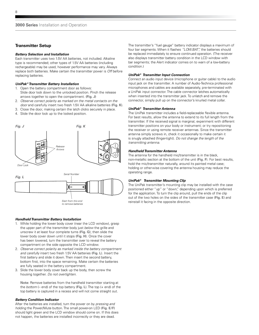
Slide door lock down to the unlocked position. Pinch the release arrows together to open the compartment. (Fig. J)
2.Observe correct polarity as marked on the metal contacts on the door and carefully insert two fresh 1.5V AA alkaline batteries (Fig. K).
3.Close the door, making certain the latch clicks securely in place.
4.Slide the door lock up to the locked position.
Fig. J | Fig. K |
Release
Arrows
Door Lock
The transmitter’s “fuel gauge” battery indicator displays a maximum of four bar segments. When it flashes “LOW.BAT”, the batteries should be replaced immediately to ensure continued operation. (The receiver also displays transmitter battery condition in the LCD window with bar segments; the Alert indicator comes on to warn of a
UniPak® Transmitter Input Connection
Connect an audio input device (microphone or guitar cable) to the audio input jack on the transmitter. A number of
UniPak® Transmitter Antenna
The UniPak transmitter includes a
is snugly attached
Handheld Transmitter Antenna
The antenna for the handheld mic/transmitter is in the black,
Fig. L
Serial Number
UniPak® Transmitter Mounting Clip
Start from this end to remove batteries
The UniPak transmitter’s mounting clip may be installed with the case positioned either “up” or “down,” depending upon which is preferred for the application. To turn the clip around, pull the ends of the clip out of the two holes on the sides of the transmitter case (Fig. E) and reinstall it facing in the opposite direction.
Handheld Transmitter Battery Installation
1.While holding the lower body cover (near the LCD window), grasp the upper part of the transmitter body just below the grille and unscrew it at least four complete turns (Fig. G); then slide the lower body cover down until it stops (Fig. H). Once the cover has been lowered, turn the transmitter over to reveal the battery compartment on the side opposite the LCD window.
2.Observe correct polarity as marked inside the battery compartment and carefully insert two fresh 1.5V AA batteries (Fig. L). Insert the first battery and slide it down. Then insert the second battery, bottom first, into the space remaining. Make certain the batteries are fully seated in the battery compartment.
3.Slide the lower body cover back up the body, then screw the housing together. Do not overtighten.
Note: Remove batteries from the handheld transmitter starting at the bottom (– end) of the top battery (Fig. L). The top (+ end) of the top battery is captured in a recess and will not come straight out.
Battery Condition Indicator
After the batteries are installed, turn the power on by pressing and holding the Power/Mute button. The small