3
3000 Series Installation and Operation
is detected, reducing the possibility of interference. As a result, 3000 Series transmitters and receivers must be used together and should not be used with components from other
Please note that in
Receiver Installation
Location
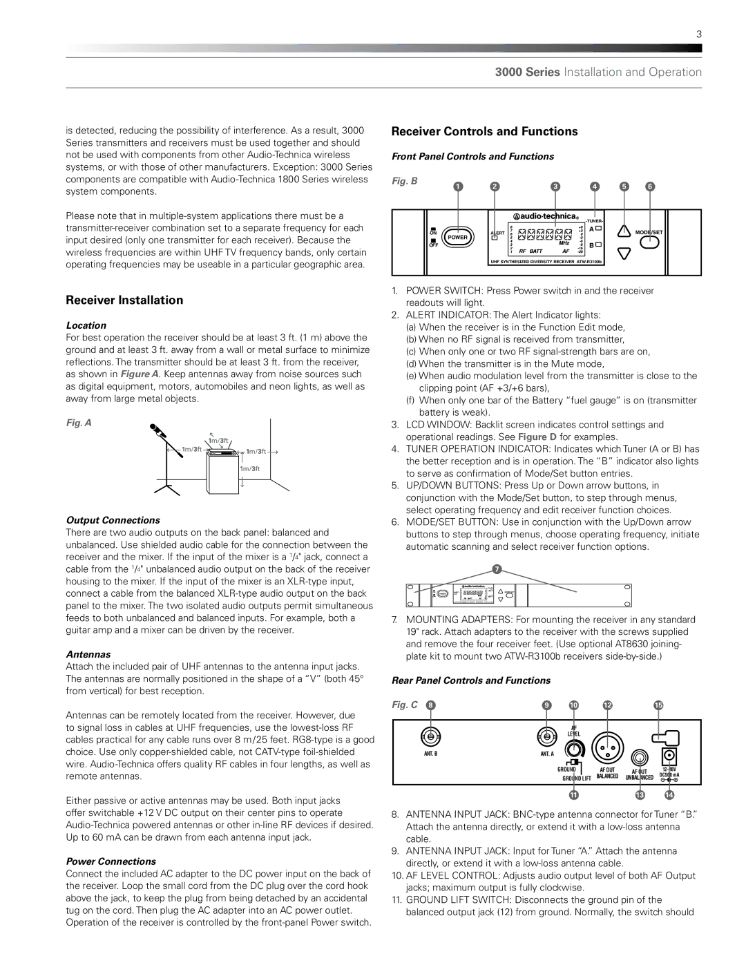
For best operation the receiver should be at least 3 ft. (1 m) above the ground and at least 3 ft. away from a wall or metal surface to minimize reflections. The transmitter should be at least 3 ft. from the receiver, as shown in Figure A. Keep antennas away from noise sources such as digital equipment, motors, automobiles and neon lights, as well as away from large metal objects.
Fig. A
Output Connections
There are two audio outputs on the back panel: balanced and unbalanced. Use shielded audio cable for the connection between the receiver and the mixer. If the input of the mixer is a 1/4" jack, connect a cable from the 1/4" unbalanced audio output on the back of the receiver housing to the mixer. If the input of the mixer is an
Antennas
Attach the included pair of UHF antennas to the antenna input jacks. The antennas are normally positioned in the shape of a “V” (both 45° from vertical) for best reception.
Antennas can be remotely located from the receiver. However, due to signal loss in cables at UHF frequencies, use the
Either passive or active antennas may be used. Both input jacks offer switchable +12 V DC output on their center pins to operate
Power Connections
Connect the included AC adapter to the DC power input on the back of the receiver. Loop the small cord from the DC plug over the cord hook above the jack, to keep the plug from being detached by an accidental tug on the cord. Then plug the AC adapter into an AC power outlet.
Operation of the receiver is controlled by the
Receiver Controls and Functions |
|
|
| ||||
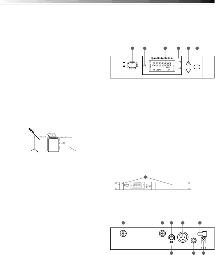
Front Panel Controls and Functions |
|
|
| ||||
Fig. B |
| 1 | 2 | 3 | 4 | 5 | 6 |
|
| ||||||
|
|
|
|
|
|
| |
| ON |
| ALERT |
| A |
| MODE/SET |
| POWER |
|
|
| |||
|
|
|
|
|
|
| |
| OFF |
|
|
| B |
|
|
|
|
| UHF SYNTHESIZED DIVERSITY RECEIVER |
|
| ||
1.POWER SWITCH: Press Power switch in and the receiver readouts will light.
2.ALERT INDICATOR: The Alert Indicator lights:
(a)When the receiver is in the Function Edit mode,
(b)When no RF signal is received from transmitter,
(c)When only one or two RF
(d)When the transmitter is in the Mute mode,
(e)When audio modulation level from the transmitter is close to the clipping point (AF +3/+6 bars),
(f)When only one bar of the Battery “fuel gauge” is on (transmitter battery is weak).
3.LCD WINDOW: Backlit screen indicates control settings and operational readings. See Figure D for examples.
4.TUNER OPERATION INDICATOR: Indicates which Tuner (A or B) has the better reception and is in operation. The “B” indicator also lights
to serve as confirmation of Mode/Set button entries.
5.UP/DOWN BUTTONS: Press Up or Down arrow buttons, in conjunction with the Mode/Set button, to step through menus, select operating frequency and edit receiver function choices.
6.MODE/SET BUTTON: Use in conjunction with the Up/Down arrow buttons to step through menus, choose operating frequency, initiate automatic scanning and select receiver function options.
7 |
|
|
| |
ON | ALERT | A | MODE/SET |
| POWER |
|
|
OFF |
| B |
|
UHF SYNTHESIZED DIVERSITY RECEIVER
7.MOUNTING ADAPTERS: For mounting the receiver in any standard 19" rack. Attach adapters to the receiver with the screws supplied and remove the four receiver feet. (Use optional AT8630 joining- plate kit to mount two
Rear Panel Controls and Functions
Fig. C 8 | 9 | 10 | 12 |
| 15 |
|
| AF |
|
|
|
|
| LEVEL |
|
|
|
ANT. B | ANT. A |
|
|
|
|
|
| GROUND | AF OUT | AF OUT | 12~18V |
|
| GROUND LIFT | BALANCED | UNBALANCED | DC500 mA |
|
| 11 |
| 13 | 14 |
8.ANTENNA INPUT JACK:
9.ANTENNA INPUT JACK: Input for Tuner “A.” Attach the antenna directly, or extend it with a
10.AF LEVEL CONTROL: Adjusts audio output level of both AF Output jacks; maximum output is fully clockwise.
11.GROUND LIFT SWITCH: Disconnects the ground pin of the balanced output jack (12) from ground. Normally, the switch should