5
3000 Series Installation and Operation
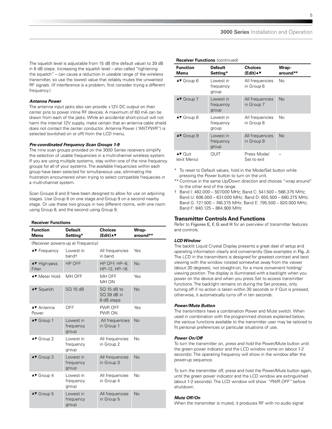
The squelch level is adjustable from 15 dB (the default value) to 39 dB in 6 dB steps. Increasing the squelch level – also called “tightening the squelch” – can cause a reduction in useable range of the wireless
Receiver Functions (continued)
Function | Default | Choices | Wrap- |
Menu | Setting* | (Edit)▲▼ | around** |
transmitter, so use the lowest value that reliably mutes the unwanted RF signals. (If interference is a problem, first consider trying a different frequency.)
Antenna Power
The antenna input jacks also can provide +12V DC output on their center pins to power inline RF devices. A maximum of 60 mA can be drawn from each of the jacks. While an accidental
Pre-coordinated Frequency Scan Groups 1-9
The nine scan groups provided on the 3000 Series receivers simplify the selection of usable frequencies in a
▲▼ Group 6
▲▼ Group 7
▲▼ Group 8
▲▼ Group 9
▲▼ Quit (exit Menu)
Lowest in frequency group
Lowest in frequency group
Lowest in frequency group
Lowest in frequency group
QUIT
All frequencies in Group 6
All frequencies in Group 7
All frequencies in Group 8
All frequencies in Group 9
Press Mode/ Set to exit
No
No
No
No
–
group have been selected for simultaneous use, eliminating the frustration encountered when trying to select compatible frequecies in a
Scan Groups 8 and 9 have been designed to allow for use on adjoining stages. Use Group 8 on one stage and Group 9 on a second nearby stage. Or use these two groups in two different rooms, with one room using Group 8, and the second using Group 9.
*To reset to Default values, hold in the Mode/Set button while pressing the Power button to turn on the unit.
**Continue in the same Up/Down direction and choices “wrap around” to the other end of the range.
†Band I: 482.000 – 507.000 MHz; Band C: 541.500 – 566.375 MHz;
Band U: 606.000 – 631.000 MHz; Band D: 655.500 – 680.375 MHz;
Band G: 721.500 – 746.375 MHz; Band E: 795.500 – 820.000 MHz;
Band F: 840.125 – 864.900 MHz
Receiver Functions
Function | Default | Choices | Wrap- |
Menu | Setting* | (Edit)▲▼ | around** |
|
|
| |
(Receiver |
|
| |
▲▼ Frequency | Lowest in | All frequencies | Yes |
| band† | in band |
|
▲▼ | HP OFF | HP OFF, | No |
Filter |
|
| |
▲▼ Meter Hold | MH OFF | MH OFF | Yes |
|
| MH ON |
|
▲▼ Squelch | SQ 15 dB | SQ 15 dB to | No |
|
| SQ 39 dB in |
|
|
| 6 dB steps |
|
▲▼ Antenna | OFF | PWR OFF | Yes |
Power |
| PWR ON |
|
▲▼ Group 1 | Lowest in | All frequencies | No |
| frequency | in Group 1 |
|
| group |
|
|
▲▼ Group 2 | Lowest in | All frequencies | No |
| frequency | in Group 2 |
|
| group |
|
|
▲▼ Group 3 | Lowest in | All frequencies | No |
| frequency | in Group 3 |
|
| group |
|
|
▲▼ Group 4 | Lowest in | All frequencies | No |
| frequency | in Group 4 |
|
| group |
|
|
▲▼ Group 5 | Lowest in | All frequencies | No |
| frequency | in Group 5 |
|
| group |
|
|
Transmitter Controls And Functions
Refer to Figures E, F, G and H for an overview of transmitter features and controls.
LCD Window
The backlit Liquid Crystal Display presents a great deal of setup and operating information clearly and conveniently (See examples in Fig. J). The LCD in the transmitters is designed for greatest contrast and best viewing with the window rotated somewhat away from the viewer (about 30 degrees), not
Power/Mute Button
The transmitters have a combination Power and Mute switch. When used in combination with the programmed choices explained below, the various functions available to the transmitter user may be tailored to fit personal preferences or particular situations of use.
Power On/Off
To turn the transmitter on, press and hold the Power/Mute button until the green power indicator and the LCD window come on (about
To turn the transmitter off, press and hold the Power/Mute button again, until the green power indicator and the LCD window are extinguished (about
Mute Off/On
When the transmitter is muted, it produces RF with no audio signal
