Receiver Controls and Functions
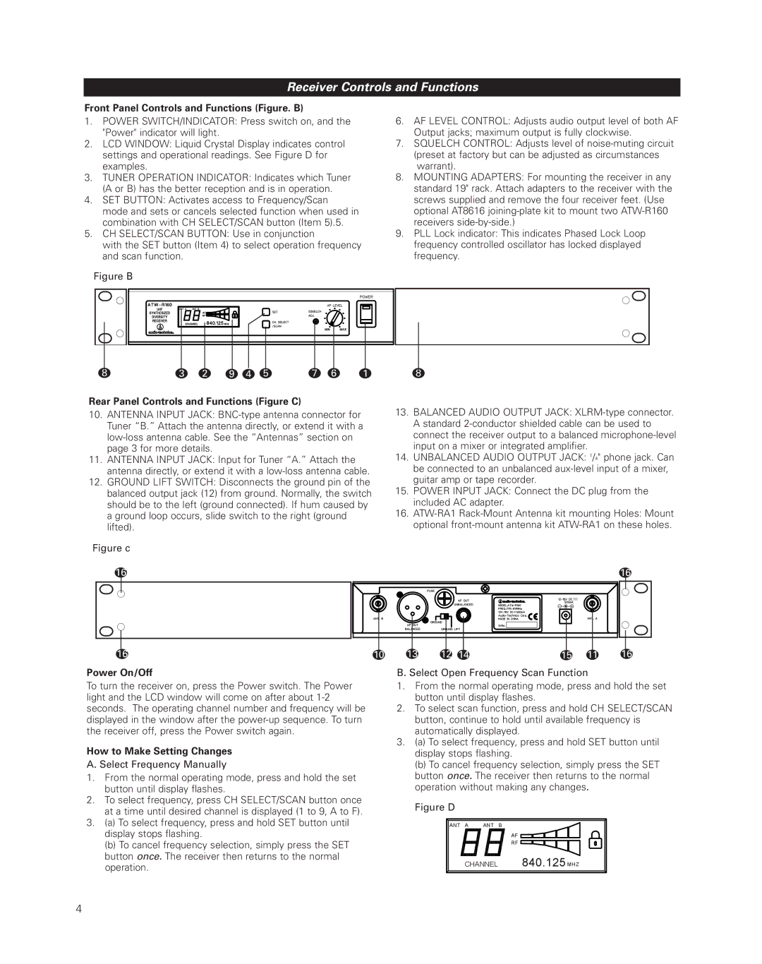
Front Panel Controls and Functions (Figure. B)
1.POWER SWITCH/INDICATOR: Press switch on, and the "Power" indicator will light.
2.LCD WINDOW: Liquid Crystal Display indicates control settings and operational readings. See Figure D for examples.
3.TUNER OPERATION INDICATOR: Indicates which Tuner (A or B) has the better reception and is in operation.
4.SET BUTTON: Activates access to Frequency/Scan
mode and sets or cancels selected function when used in combination with CH SELECT/SCAN button (Item 5).5.
5.CH SELECT/SCAN BUTTON: Use in conjunction
with the SET button (Item 4) to select operation frequency and scan function.
Figure B
6.AF LEVEL CONTROL: Adjusts audio output level of both AF Output jacks; maximum output is fully clockwise.
7.SQUELCH CONTROL: Adjusts level of noise-muting circuit (preset at factory but can be adjusted as circumstances warrant).
8.MOUNTING ADAPTERS: For mounting the receiver in any standard 19" rack. Attach adapters to the receiver with the screws supplied and remove the four receiver feet. (Use optional AT8616 joining-plate kit to mount two ATW-R160 receivers side-by-side.)
9.PLL Lock indicator: This indicates Phased Lock Loop frequency controlled oscillator has locked displayed frequency.
8 | 3 | 2 | 9 | 4 | 5 | 7 | 6 | 1 | 8 |
Rear Panel Controls and Functions (Figure C)
10.ANTENNA INPUT JACK:
11.ANTENNA INPUT JACK: Input for Tuner “A.” Attach the antenna directly, or extend it with a
12.GROUND LIFT SWITCH: Disconnects the ground pin of the balanced output jack (12) from ground. Normally, the switch should be to the left (ground connected). If hum caused by a ground loop occurs, slide switch to the right (ground lifted).
Figure c
16
13.BALANCED AUDIO OUTPUT JACK: XLRM-type connector. A standard 2-conductor shielded cable can be used to connect the receiver output to a balanced microphone-level input on a mixer or integrated amplifier.
14.UNBALANCED AUDIO OUTPUT JACK: 1/4" phone jack. Can be connected to an unbalanced aux-level input of a mixer, guitar amp or tape recorder.
15.POWER INPUT JACK: Connect the DC plug from the included AC adapter.
16.
16
16
Power On/Off
To turn the receiver on, press the Power switch. The Power light and the LCD window will come on after about
How to Make Setting Changes
A. Select Frequency Manually
1.From the normal operating mode, press and hold the set button until display flashes.
2.To select frequency, press CH SELECT/SCAN button once at a time until desired channel is displayed (1 to 9, A to F).
3.(a) To select frequency, press and hold SET button until display stops flashing.
(b) To cancel frequency selection, simply press the SET button once. The receiver then returns to the normal operation.
10 | 13 | 12 | 14 | 15 | 11 | 16 |
B. Select Open Frequency Scan Function
1.From the normal operating mode, press and hold the set button until display flashes.
2.To select scan function, press and hold CH SELECT/SCAN button, continue to hold until available frequency is automatically displayed.
3.(a) To select frequency, press and hold SET button until display stops flashing.
(b) To cancel frequency selection, simply press the SET button once. The receiver then returns to the normal operation without making any changes.
Figure D
ANT A | ANT B |
AF
RF
CHANNEL 840.125 MHZ
4