E. Controls, Indicators, and Connectors
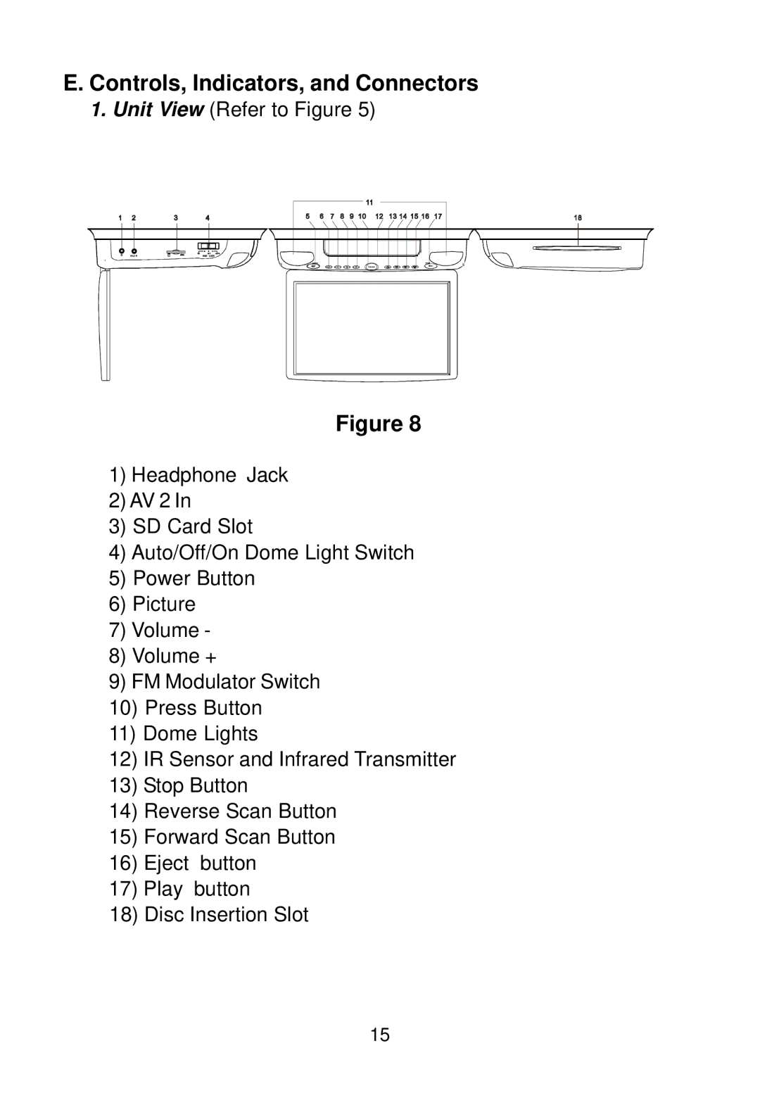
1.Unit View (Refer to Figure 5)
Figure 8
1)Headphone Jack
2)AV 2 In
3)SD Card Slot
4)Auto/Off/On Dome Light Switch
5)Power Button
6)Picture
7)Volume -
8)Volume +
9)FM Modulator Switch
10)Press Button
11)Dome Lights
12)IR Sensor and Infrared Transmitter
13)Stop Button
14)Reverse Scan Button
15)Forward Scan Button
16)Eject button
17)Play button
18)Disc Insertion Slot
15
