VOD701
| Power Connector |
IR LED: | 4 Pin |
|
Clean the IR Receiver Window on the front of the VCP. Remove Adhesive Backing and Apply IR LED to IR Window on the Face of the VCP.
| Red RCA (Audio Right) | Hard Wired FM Modulator Output |
|
| * REFER TO PAGE 8 FOR FURTHER DETAILS |
|
|
|
| ||
| White RCA (Audio Left) | 12 VDC Power and Ground |
|
|
|
| Yellow RCA (Video) |
|
|
| |
|
|
| Satalite |
| |
|
| FM | Radio | Am/Fm | TO |
| 14Pin FMM Cable |
| Antenna | FACTORY | |
| Modulator |
|
| RADIO | |
| Item #8 |
|
| Dash Radio |
|
|
|
|
|
| |
"Y" Adapter | Accessory |
|
|
|
|
for use with |
|
|
|
| |
Harness - Optional |
|
|
|
| |
Installations | (P/N:8010730) |
|
|
|
|
Item# 5 |
|
|
|
|
|
|
|
| Optional Remote Headphone Stations | ||
|
| Dome Light |
|
|
|
|
| Power Source |
| Green | Stereo |
|
|
|
| ||
|
|
|
| (Right+) | Headphone Jack |
| Power Harness |
|
| Black | Stereo |
|
|
| (Ground) | Headphone Jack | |
| Item #3 |
|
|
|
|
2 | 1 | Gray | |
(Left+) | |||
|
|
Line |
Line |
Line
To Secondary AV Monitor
| INPUT | 12 VDC Power and Ground | |
|
| ||
|
| VIDEO | |
|
|
| |
LINE |
|
| Auxillary |
OUT | Patch Cord |
| |
VIDEO |
| video display | |
RCA Male to Male |
| ||
(Yellow) |
|
|
|
Power Harness
Item #3
CHOKE |
TO
OPTIONAL ADDITIONAL MONITOR
Battery12V
Second IR
Input
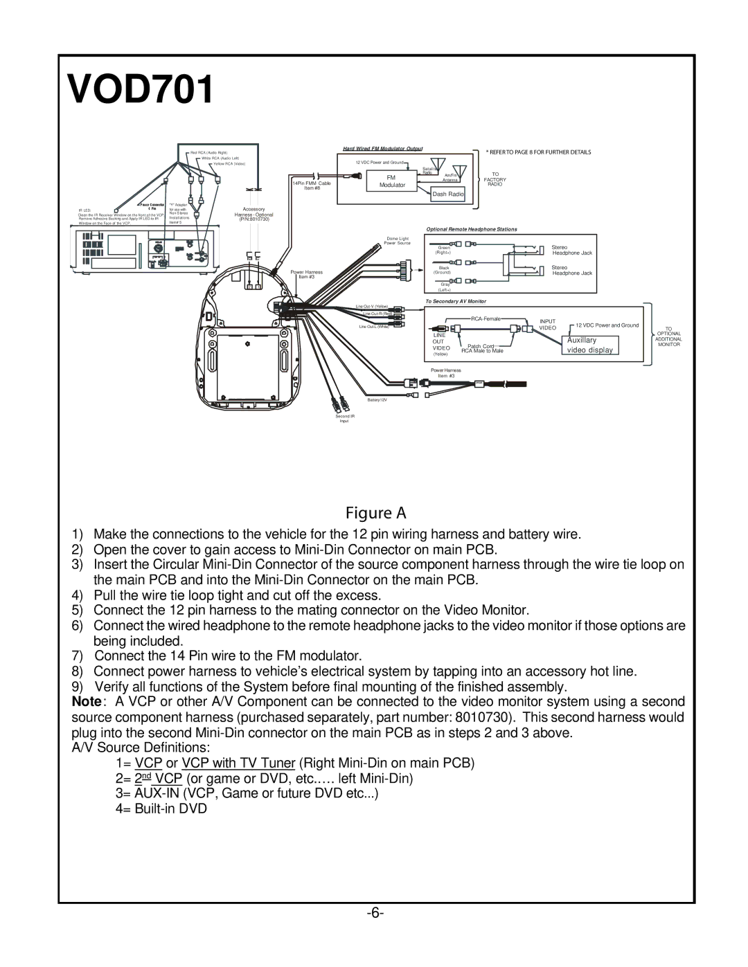
Figure A
1)Make the connections to the vehicle for the 12 pin wiring harness and battery wire.
2)Open the cover to gain access to
3)Insert the Circular
4)Pull the wire tie loop tight and cut off the excess.
5)Connect the 12 pin harness to the mating connector on the Video Monitor.
6)Connect the wired headphone to the remote headphone jacks to the video monitor if those options are being included.
7)Connect the 14 Pin wire to the FM modulator.
8)Connect power harness to vehicle’s electrical system by tapping into an accessory hot line.
9)Verify all functions of the System before final mounting of the finished assembly.
Note: A VCP or other A/V Component can be connected to the video monitor system using a second
source component harness (purchased separately, part number: 8010730). This second harness would plug into the second
A/V Source Definitions:
1= VCP or VCP with TV Tuner (Right
3=