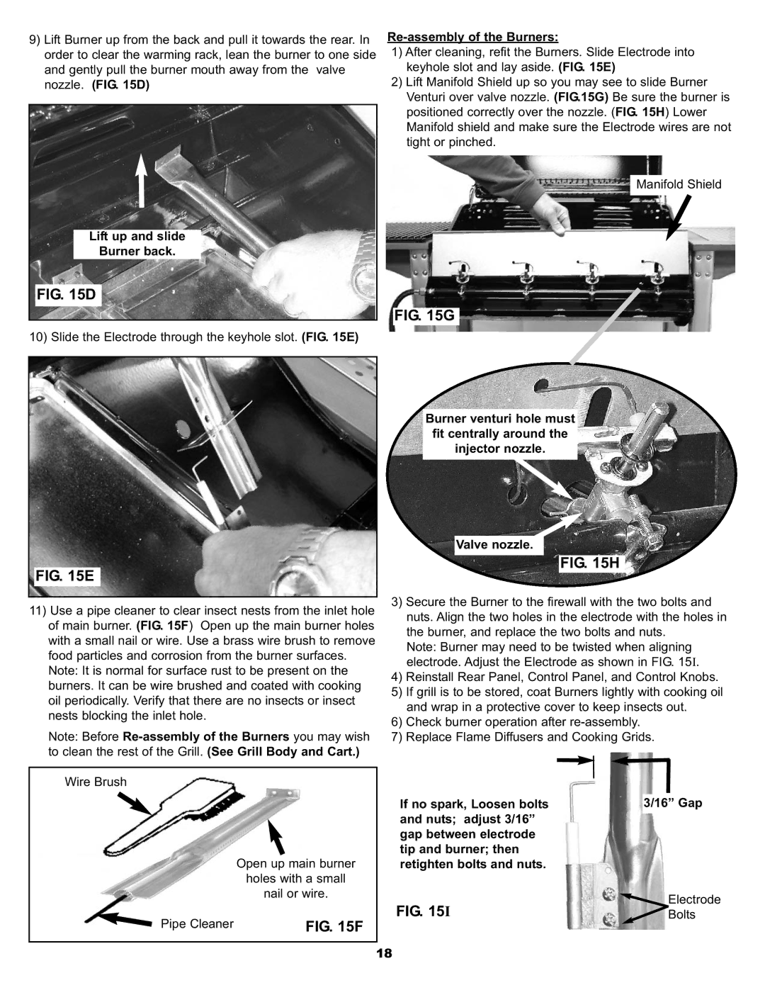
9)Lift Burner up from the back and pull it towards the rear. In order to clear the warming rack, lean the burner to one side and gently pull the burner mouth away from the valve nozzle. (FIG. 15D)
Lift up and slide
Burner back.
FIG. 15D
10) Slide the Electrode through the keyhole slot. (FIG. 15E)
FIG. 15E
11)Use a pipe cleaner to clear insect nests from the inlet hole of main burner. (FIG. 15F) Open up the main burner holes with a small nail or wire. Use a brass wire brush to remove food particles and corrosion from the burner surfaces.
Note: It is normal for surface rust to be present on the burners. It can be wire brushed and coated with cooking oil periodically. Verify that there are no insects or insect nests blocking the inlet hole.
Note: Before
Wire Brush
Re-assembly of the Burners:
1)After cleaning, refit the Burners. Slide Electrode into keyhole slot and lay aside. (FIG. 15E)
2)Lift Manifold Shield up so you may see to slide Burner Venturi over valve nozzle. (FIG.15G) Be sure the burner is positioned correctly over the nozzle. (FIG. 15H) Lower Manifold shield and make sure the Electrode wires are not tight or pinched.
Manifold Shield
FIG. 15G
Burner venturi hole must fit centrally around the injector nozzle.
Valve nozzle.
FIG. 15H
3)Secure the Burner to the firewall with the two bolts and nuts. Align the two holes in the electrode with the holes in the burner, and replace the two bolts and nuts.
Note: Burner may need to be twisted when aligning electrode. Adjust the Electrode as shown in FIG. 15I.
4)Reinstall Rear Panel, Control Panel, and Control Knobs.
5)If grill is to be stored, coat Burners lightly with cooking oil and wrap in a protective cover to keep insects out.
6)Check burner operation after
7)Replace Flame Diffusers and Cooking Grids.
Open up main burner
holes with a small
nail or wire.
Pipe Cleaner |
|
|
| FIG. 15F | |
|
|
|
If no spark, Loosen bolts and nuts; adjust 3/16” gap between electrode tip and burner; then retighten bolts and nuts.
FIG. 15I
3/16” Gap
Electrode
![]() Bolts
Bolts
18