Chapter 2 | Installation |
|
|
|
|
| ||
|
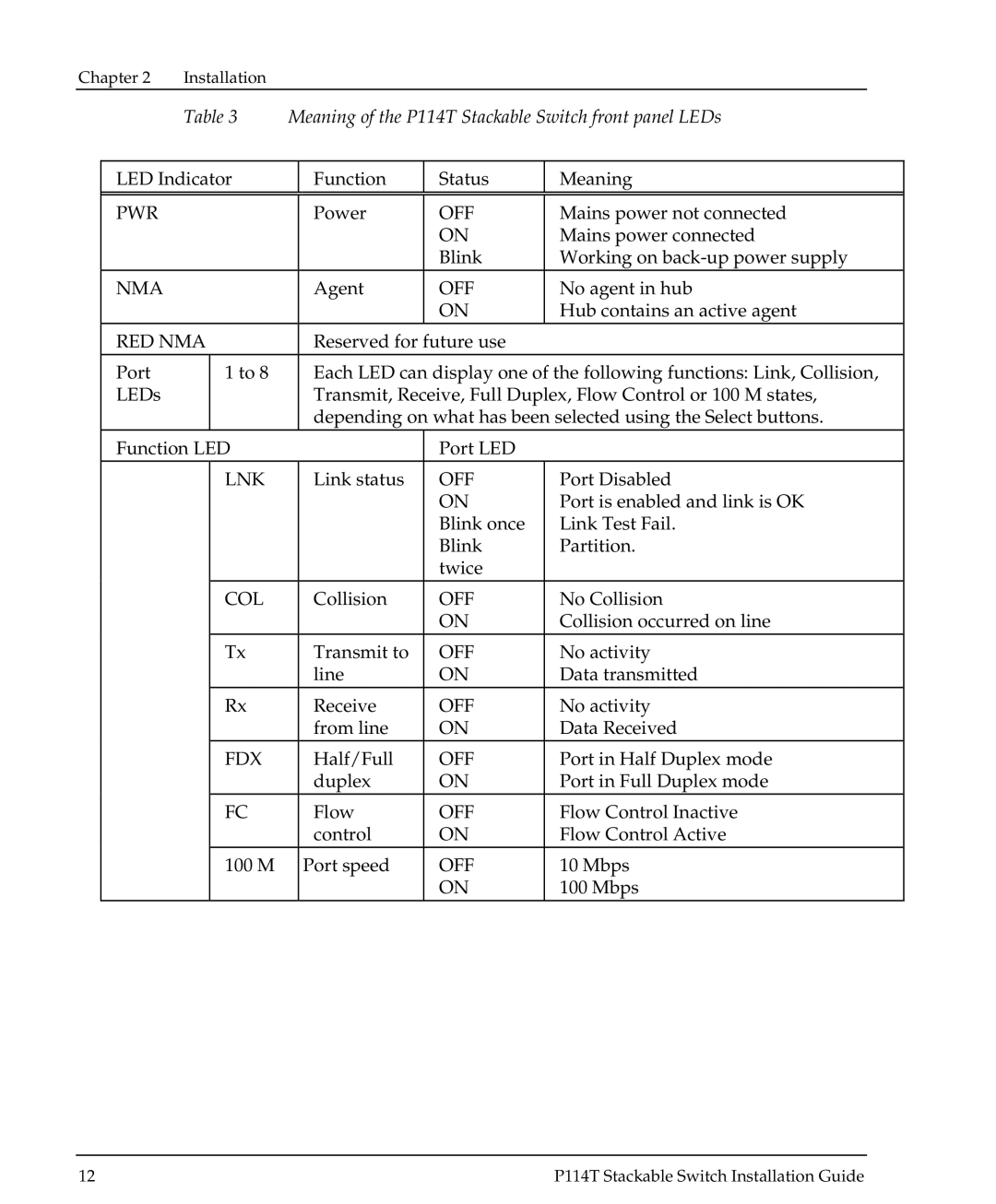
| Table 3 | Meaning of the P114T Stackable Switch front panel LEDs | |||||
|
|
|
|
|
|
| ||
| LED Indicator |
| Function | Status | Meaning | |||
|
|
|
|
|
|
|
| |
| PWR |
|
|
| Power | OFF | Mains power not connected | |
|
|
|
|
|
| ON | Mains power connected | |
|
|
|
|
|
| Blink | Working on | |
| NMA |
|
|
| Agent | OFF | No agent in hub | |
|
|
|
|
|
| ON | Hub contains an active agent | |
| RED NMA |
| Reserved for future use |
|
| |||
| Port |
| 1 to 8 |
| Each LED can display one of the following functions: Link, Collision, | |||
| LEDs |
|
|
| Transmit, Receive, Full Duplex, Flow Control or 100 M states, | |||
|
|
|
|
| depending on what has been selected using the Select buttons. | |||
| Function LED |
|
| Port LED |
|
| ||
|
|
| LNK |
| Link status | OFF | Port Disabled | |
|
|
|
|
|
| ON | Port is enabled and link is OK | |
|
|
|
|
|
| Blink once | Link Test Fail. | |
|
|
|
|
|
| Blink | Partition. | |
|
|
|
|
|
| twice |
|
|
|
|
| COL |
| Collision | OFF | No Collision | |
|
|
|
|
|
| ON | Collision occurred on line | |
|
|
| Tx |
| Transmit to | OFF | No activity | |
|
|
|
|
| line | ON | Data transmitted | |
|
|
| Rx |
| Receive | OFF | No activity | |
|
|
|
|
| from line | ON | Data Received | |
|
|
| FDX |
| Half/Full | OFF | Port in Half Duplex mode | |
|
|
|
|
| duplex | ON | Port in Full Duplex mode | |
|
|
| FC |
| Flow | OFF | Flow Control Inactive | |
|
|
|
|
| control | ON | Flow Control Active | |
|
|
| 100 M |
| Port speed | OFF | 10 Mbps | |
|
|
|
|
|
| ON | 100 Mbps | |
12 | P114T Stackable Switch Installation Guide |
