AXIS 262+ Installation Guide | Page 9 |
Unit Connectors
Network connector-
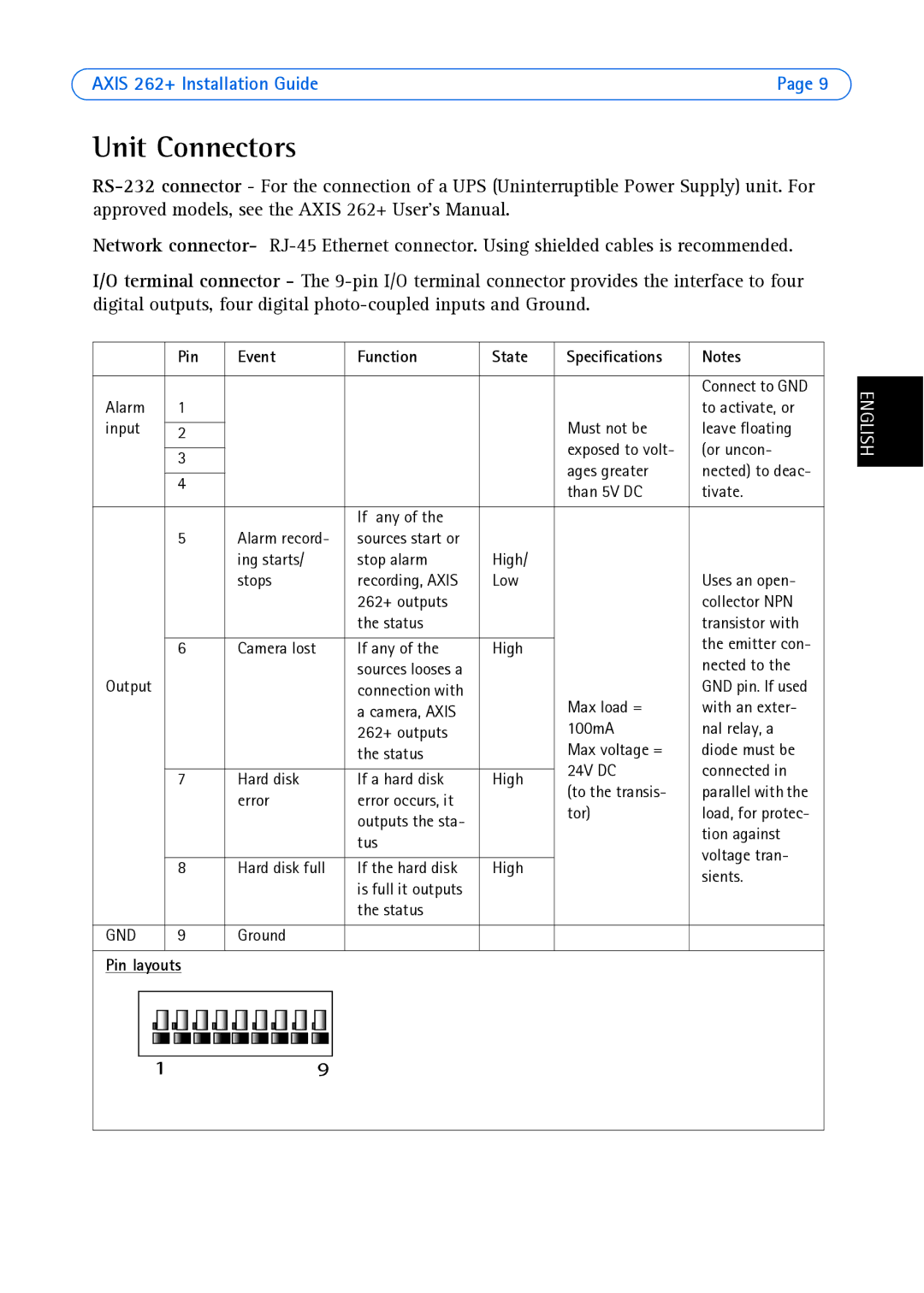
I/O terminal connector - The
| Pin | Event | Function | State | Specifications | Notes |
|
|
|
|
|
|
|
|
|
|
|
|
| Connect to GND |
Alarm | 1 |
|
|
|
| to activate, or |
input |
|
|
|
| Must not be | leave floating |
2 |
|
|
| |||
|
|
|
|
| exposed to volt- | (or uncon- |
| 3 |
|
|
| ||
|
|
|
| ages greater | nected) to deac- | |
|
|
|
|
| ||
| 4 |
|
|
| ||
|
|
|
| than 5V DC | tivate. | |
|
|
|
|
| ||
|
|
|
|
|
|
|
|
|
| If any of the |
|
|
|
| 5 | Alarm record- | sources start or |
|
|
|
|
| ing starts/ | stop alarm | High/ |
|
|
|
| stops | recording, AXIS | Low |
| Uses an open- |
|
|
| 262+ outputs |
|
| collector NPN |
|
|
| the status |
|
| transistor with |
|
|
|
|
|
| the emitter con- |
| 6 | Camera lost | If any of the | High |
| |
|
|
| sources looses a |
|
| nected to the |
Output |
|
| connection with |
|
| GND pin. If used |
|
|
| a camera, AXIS |
| Max load = | with an exter- |
|
|
| 262+ outputs |
| 100mA | nal relay, a |
|
|
| the status |
| Max voltage = | diode must be |
|
|
|
|
| 24V DC | connected in |
| 7 | Hard disk | If a hard disk | High | ||
| (to the transis- | parallel with the | ||||
|
| error | error occurs, it |
| ||
|
|
| tor) | load, for protec- | ||
|
|
| outputs the sta- |
| ||
|
|
|
|
| tion against | |
|
|
| tus |
|
| |
|
|
|
|
| voltage tran- | |
|
|
|
|
|
| |
| 8 | Hard disk full | If the hard disk | High |
| |
|
| sients. | ||||
|
|
| is full it outputs |
|
| |
|
|
|
|
|
| |
|
|
| the status |
|
|
|
|
|
|
|
|
|
|
GND | 9 | Ground |
|
|
|
|
|
|
|
|
|
|
|
Pin layouts
ENGLISH