AXIS M1143–L
Technical Specifications
Function/group | Item | Specifications |
|
|
|
| Installation, | AXIS Camera Management tool on CD and |
| management and | Configuration of backup and restore |
| maintenance | Firmware upgrades over HTTP or FTP, firmware available on www.axis.com |
|
|
|
General | Casing | Aluminium and PC/ABS |
|
| Color: White NCS S |
| Processor, | Ambarella, 256 MB RAM, 128 MB Flash |
| memory | Battery |
| Power | Power over Ethernet IEEE 802.3af Class 2 (max. 6.49W) |
| IR illumination | Highly efficient IR LEDs with adjustable intensity and angle of illumination. Range of |
|
| reach up to 25 m |
| Connectors | |
| Local storage | Micro SD/SDHC memory card slot (card not included) |
| Operating | 0 °C to 40 °C (32 °F to 122 °F), humidity 20 - 80% RH |
| conditions |
|
| Storage | |
| temperature |
|
| Approvals | CE: Emission: EN55022:2006+A1 Class B Harmonics: |
|
| Immunity: EN55024, |
|
| FCC: FCC Part 15, Subpart B, Class B demonstrated by compliance with EN55022 (CISPR |
|
| 22) |
|
| Japan: |
|
| with EN55022 (CISPR 22) |
|
| Canada: |
|
| with EN55022 (CISPR 22) |
|
| Korea: Emission: KN22 Immunity: KN24 UL: cUL, usUL |
| Dimensions | 46 x 75 x 115 mm (1.8" x 3.0" x 4.5") |
| Weight | 250g (0.21 lb.) |
| Included | Stand, Lever tool, Installation Guide, CD including installation tools and other software, |
| accessories | Windows decoder |
| Video | AXIS Camera Station - Video management software for viewing and |
| management | recording up to 100 cameras. For more software application via partners, see |
| software (not | www.axis.com/products/video/software/ |
| included) |
|
|
|
|
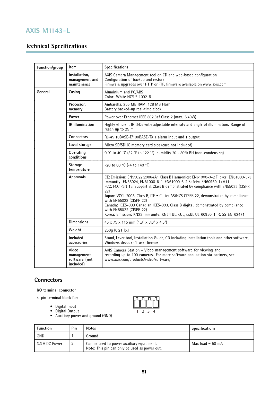
Connectors
I/O terminal connector
• | Digital Input |
|
|
|
|
|
|
|
|
|
|
|
|
|
|
|
|
|
| |
• | Digital Output | 1 2 3 4 |
|
|
|
| ||||||||||||||
• Auxiliary power and ground (GND) |
| |||||||||||||||||||
|
|
|
|
|
|
| ||||||||||||||
Function |
| Pin | Notes | Specifications | ||||||||||||||||
|
|
|
|
|
|
| ||||||||||||||
GND |
| 1 | Ground |
| ||||||||||||||||
|
|
|
|
|
| |||||||||||||||
3.3 V DC Power | 2 | Can be used to power auxiliary equipment. | Max load = 50 mA | |||||||||||||||||
|
|
| Note: This pin can only be used as power out. |
| ||||||||||||||||
|
|
|
|
|
|
|
|
|
|
|
|
|
|
|
|
|
|
|
|
|
51