AXIS Q6045–S PTZ Dome Network Camera
Hardware Overview
5.Keep the gas flowing through the camera housing for one minute before removing the chuck from the inlet valve.
6.Lift the pressure relief valve to let the overpressure out of the camera unit.
7.Repeat the filling process a total of 3 times, leaving the the camera pressurized the last time.
8.Put the caps back on the inlet valve and the pressure relief valve.
Connectors and Buttons
For technical specifications, see page 63.
Multi-connector
Terminal connector for connecting the supplied media converter switch, which provides the following signals:
•DC Power
•Network (Ethernet
•Input/Output (I/O)
The supplied
SD Card Slot
An SD card (not included) can be used for local recording with removable storage. For more information, see Technical Specifications.
NOTICE
To prevent corruption of recordings, the SD card should be unmounted before removal. To unmount, go to Setup > System Options > Storage > SD Card and click Unmount.
Control Button
The control button is used for:
•Resetting the product to factory default settings. See page 57.
•Connecting to an AXIS Video Hosting System service. See page 50. To connect, press and hold the button for about 1 second until the Status LED flashes green.
•Connecting to AXIS Internet Dynamic DNS Service. See page 50. To connect, press and hold the button for about 3 seconds.
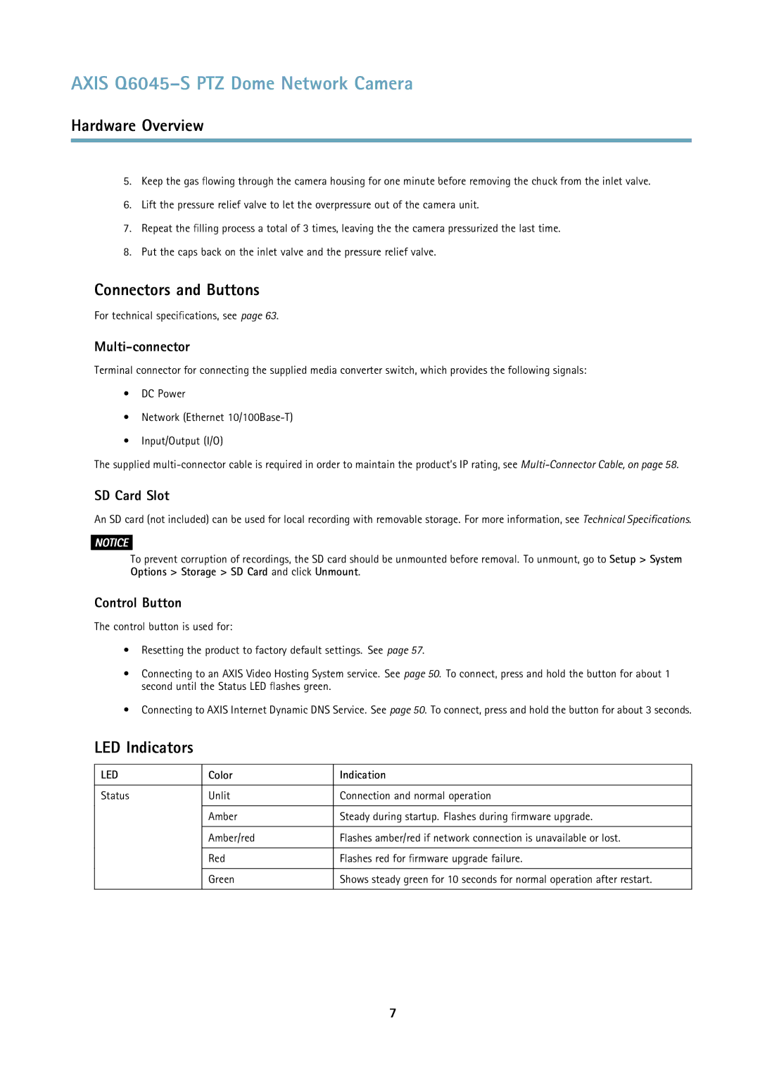
LED Indicators
LED | Color | Indication |
|
|
|
Status | Unlit | Connection and normal operation |
|
|
|
| Amber | Steady during startup. Flashes during firmware upgrade. |
|
|
|
| Amber/red | Flashes amber/red if network connection is unavailable or lost. |
|
|
|
| Red | Flashes red for firmware upgrade failure. |
|
|
|
| Green | Shows steady green for 10 seconds for normal operation after restart. |
|
|
|
7
