APPENDIX B: Cable Charts
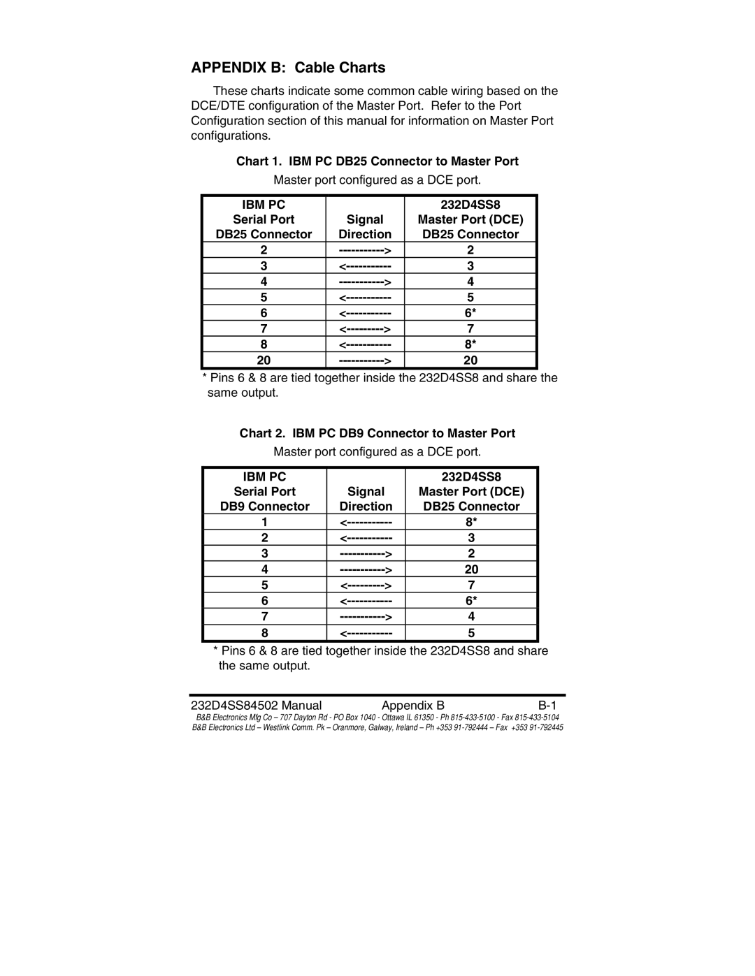
These charts indicate some common cable wiring based on the DCE/DTE configuration of the Master Port. Refer to the Port Configuration section of this manual for information on Master Port configurations.
Chart 1. IBM PC DB25 Connector to Master Port
Master port configured as a DCE port.
IBM PC |
|
| 232D4SS8 |
Serial Port |
| Signal | Master Port (DCE) |
DB25 Connector | Direction | DB25 Connector | |
2 | > | 2 | |
3 | 3 | ||
4 | > | 4 | |
5 | 5 | ||
6 | 6* | ||
7 | > | 7 | |
8 | 8* | ||
20 | > | 20 | |
*Pins 6 & 8 are tied together inside the 232D4SS8 and share the same output.
Chart 2. IBM PC DB9 Connector to Master Port
Master port configured as a DCE port.
IBM PC |
|
| 232D4SS8 |
Serial Port |
| Signal | Master Port (DCE) |
DB9 Connector | Direction | DB25 Connector | |
1 | 8* | ||
2 | 3 | ||
3 | > | 2 | |
4 | > | 20 | |
5 | > | 7 | |
6 | 6* | ||
7 | > | 4 | |
8 | 5 | ||
*Pins 6 & 8 are tied together inside the 232D4SS8 and share the same output.
232D4SS84502 Manual | Appendix B |
B&B Electronics Mfg Co – 707 Dayton Rd - PO Box 1040 - Ottawa IL 61350 - Ph
