232OPSDA
A/D0 |
| A/D1 | A/D2 | A/D3 | A/D4 | A/D5 | GND | ||
|
|
|
|
|
|
|
|
|
|
TB0 | TB1 |
| TB2 | TB3 | TB4 | TB5 |
| TB8 | |
|
|
|
|
|
|
|
|
|
|
Output |
| Input |
Current Loop | Loop | Current Loop |
Transmitter |
| Receiver |
Return |
| Out |
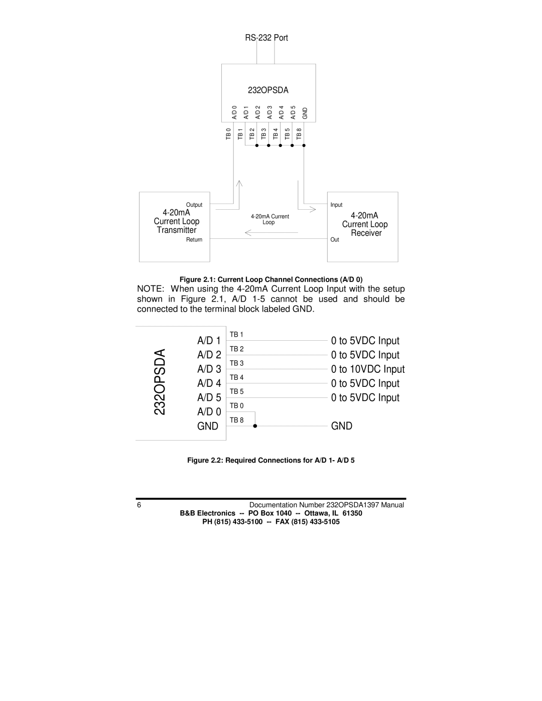
Figure 2.1: Current Loop Channel Connections (A/D 0)
NOTE: When using the
232OPSDA
A/D 1 A/D 2 A/D 3 A/D 4 A/D 5 A/D 0
GND
TB 1
TB 2
TB 3
TB 4
TB 5
TB 0
TB 8
0 to 5VDC Input
0 to 5VDC Input
0 to 10VDC Input
0 to 5VDC Input
0 to 5VDC Input
GND
Figure 2.2: Required Connections for A/D 1- A/D 5
6Documentation Number 232OPSDA1397 Manual
B&B Electronics
PH (815)
