Chapter 2: Connections
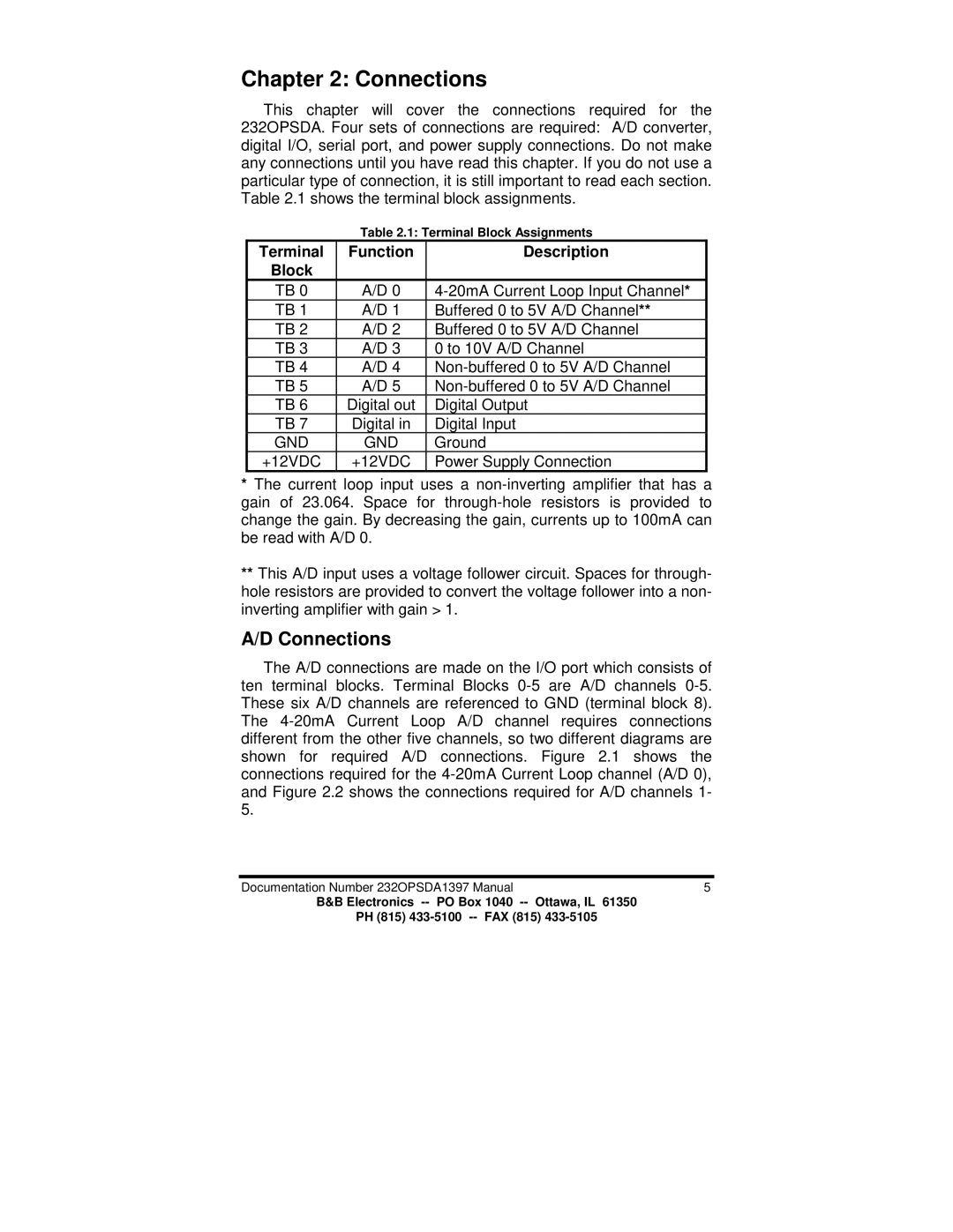
This chapter will cover the connections required for the 232OPSDA. Four sets of connections are required: A/D converter, digital I/O, serial port, and power supply connections. Do not make any connections until you have read this chapter. If you do not use a particular type of connection, it is still important to read each section. Table 2.1 shows the terminal block assignments.
Table 2.1: Terminal Block Assignments
Terminal | Function | Description |
Block |
|
|
TB 0 | A/D 0 | |
TB 1 | A/D 1 | Buffered 0 to 5V A/D Channel** |
TB 2 | A/D 2 | Buffered 0 to 5V A/D Channel |
TB 3 | A/D 3 | 0 to 10V A/D Channel |
TB 4 | A/D 4 | |
TB 5 | A/D 5 | |
TB 6 | Digital out | Digital Output |
TB 7 | Digital in | Digital Input |
GND | GND | Ground |
+12VDC | +12VDC | Power Supply Connection |
*The current loop input uses a
**This A/D input uses a voltage follower circuit. Spaces for through- hole resistors are provided to convert the voltage follower into a non- inverting amplifier with gain > 1.
A/D Connections
The A/D connections are made on the I/O port which consists of ten terminal blocks. Terminal Blocks
Documentation Number 232OPSDA1397 Manual | 5 |
B&B Electronics
PH (815)
