3PCI2 specifications
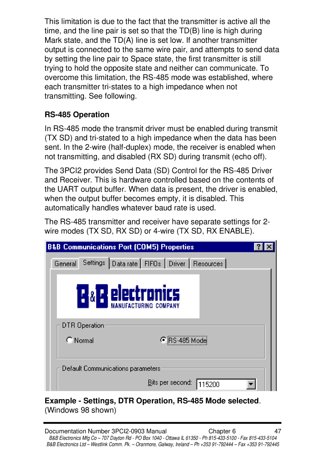
B&B Electronics has long been a leader in the field of industrial networking solutions, and their 3PCI2 serial communication card exemplifies this expertise. The 3PCI2 is a dual-port PCI serial communications interface designed to provide PC systems with reliable and efficient connectivity to serial devices. This card is particularly useful for applications requiring multiple serial device connections, making it a favorite among developers and engineers.One of the main features of the 3PCI2 is its ability to support two independent, programmable serial ports. These ports can handle RS-232, RS-422, or RS-485 communication, allowing for flexible connection options based on specific application needs. This versatility is essential in industries such as factory automation, transportation, and telecommunications, where different devices may require distinct communication standards.
The 3PCI2 utilizes advanced technology that ensures high-speed data transfer rates, reaching up to 115.2 kbps. This speed, combined with the card's reliable architecture, minimizes latency and ensures smooth communication between the PC and connected devices. Additionally, the use of direct memory access (DMA) capabilities enhances performance by allowing data to be transferred directly between the serial ports and memory without involving the CPU, thereby reducing system overhead.
Another notable characteristic of the 3PCI2 is its plug-and-play compatibility. Installation is straightforward, as it can be easily inserted into any available PCI slot on a standard PC motherboard. The card is also supported by a comprehensive driver package compatible with various operating systems, ensuring seamless integration into existing systems.
Furthermore, the 3PCI2 features high-quality signal integrity and noise immunity, which are critical in industrial environments where electromagnetic interference can impact performance. The card is designed with robust components to withstand harsh conditions, making it reliable for long-term use in demanding applications.
Overall, B&B Electronics’ 3PCI2 serial communication card stands out for its combination of features, versatile connectivity options, and robust performance. Its ability to provide reliable, high-speed communication in a dual-port configuration makes it an excellent choice for industries that rely on effective serial communication solutions. As technology continues to advance, the 3PCI2 remains a relevant and dependable option for developers looking to enhance their systems with reliable serial connectivity.

