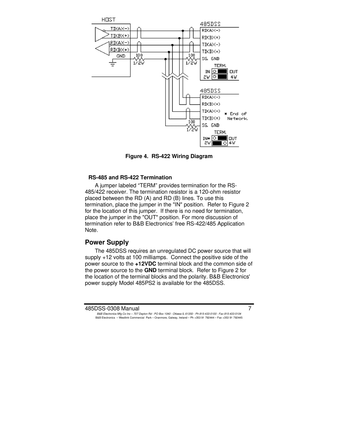
Figure 4. RS-422 Wiring Diagram
RS-485 and RS-422 Termination
A jumper labeled “TERM” provides termination for the RS- 485/422 receiver. The termination resistor is a
Power Supply
The 485DSS requires an unregulated DC power source that will supply +12 volts at 100 milliamps. Connect the positive side of the power source to the +12VDC terminal block and the common side of the power source to the GND terminal block. Refer to Figure 2 for the location of the terminal blocks and the polarity. B&B Electronics' power supply Model 485PS2 is available for the 485DSS.
7 |
B&B Electronics Mfg Co Inc – 707 Dayton Rd - PO Box 1040 - Ottawa IL 61350 - Ph
